Application method of scaffold in-situ tying device

A kind of scaffolding and in-situ technology, which is applied to the accessories of scaffolding, building structure support, building structure support, etc., can solve the problems of difficult to guarantee the quality of stone curtain wall installation and high construction risk, so as to avoid potential safety hazards, ensure the overall effect, The effect of improving firmness

Pending Publication Date: 2019-03-12
SHANGHAI BUILDING DECORATION ENG GRP
View PDF7 Cites 1 Cited by
  • Summary
  • Abstract
  • Description
  • Claims
  • Application Information

AI Technical Summary

Problems solved by technology

[0006] In view of the conflict between the location of the existing scaffolding wall parts and the installation position of the curtain wall unit plate, some curtain wall unit plates need to be installed after the scaffolding is removed, resulting in a relatively high construction risk, and the installation quality of the stone curtain wall is difficult to guarantee. , the object of the present invention is to provide a method for using the in-situ knotting device for scaffolding. The in-situ knotting device for the scaffold replaces the conventional knotting points of the scaffolding wall parts to the pre-installed two adjacent curtain wall unit panels. The location of the horizontal joints between them avoids potential safety hazards and improves the firmness of the installation of the curtain wall unit panels; and the stone curtain wall can be installed sequentially from bottom to top, ensuring the flatness of the surface of the stone curtain wall and effectively controlling the width of the horizontal joints

Method used


Image

  • Application method of scaffold in-situ tying device
  • Application method of scaffold in-situ tying device
  • Application method of scaffold in-situ tying device

Examples


Embodiment 1

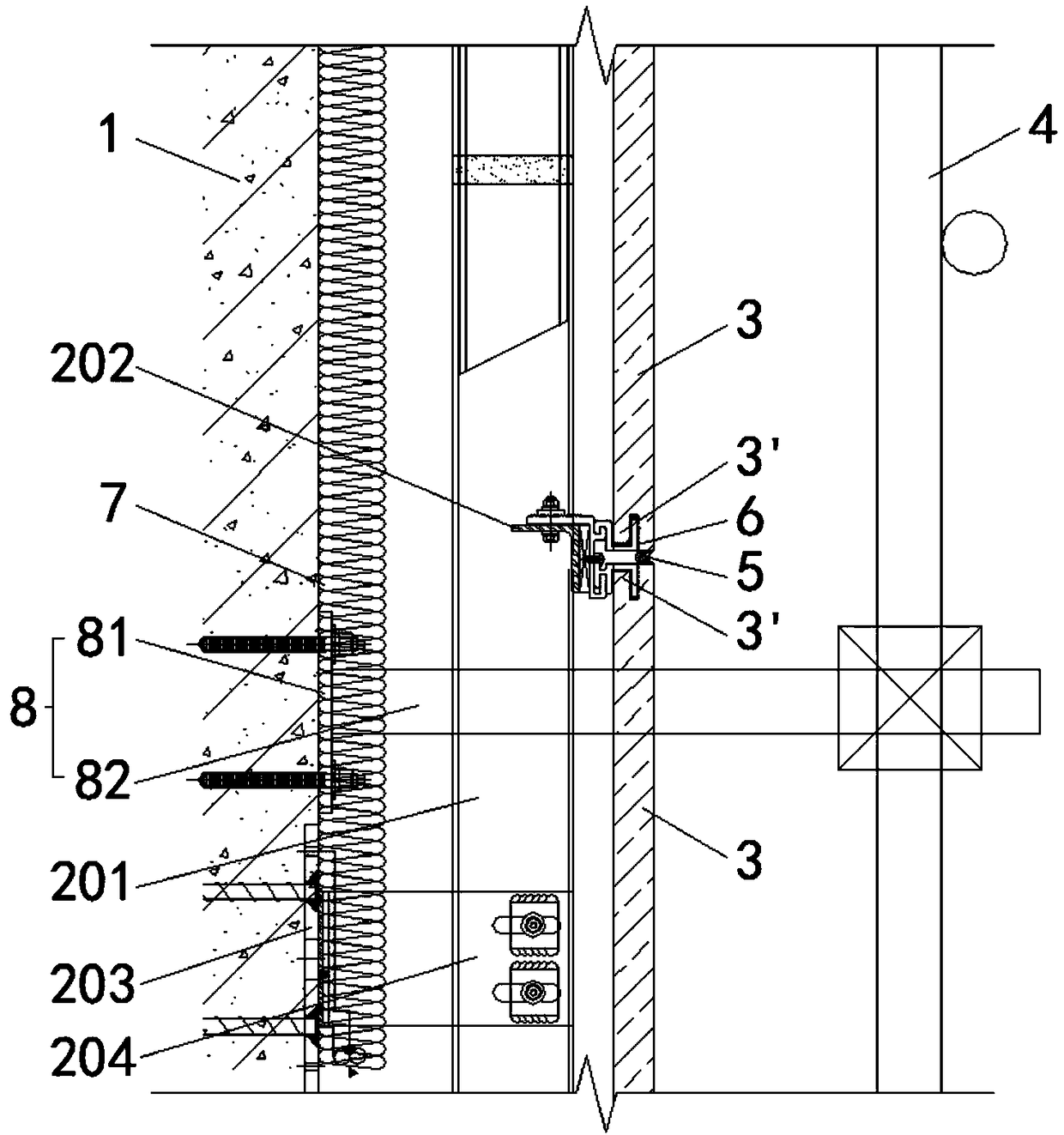
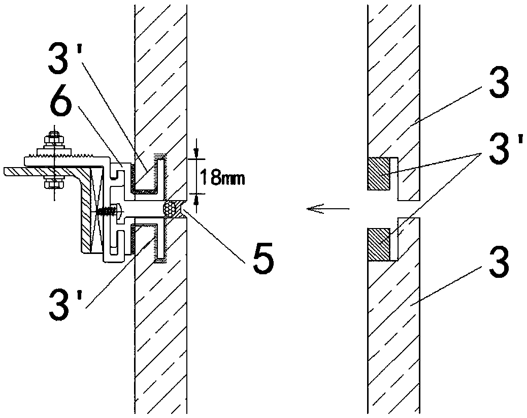
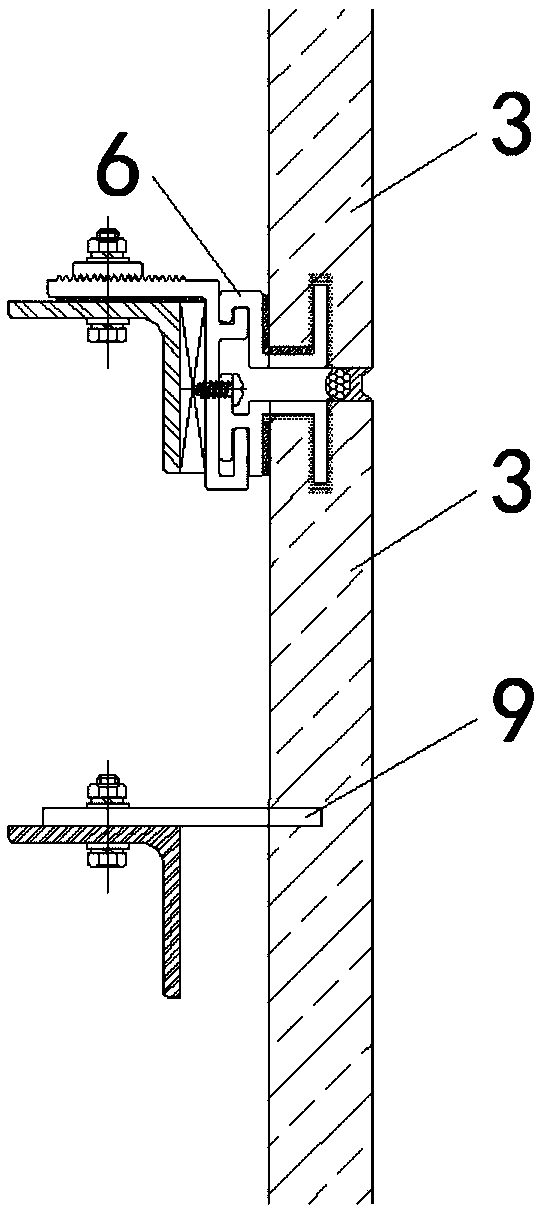
[0039] Such as figure 1 As shown, a plurality of rear embedded parts 203 arranged according to the position of the pre-installed main keel 201 are anchored to the reinforced concrete beams and columns of the building base 1 through chemical anchor bolts, and the main keel 201 and the secondary keel 202 are installed outside the building base 1, The main keel 201 is fixed to the rear embedded part 203 through the corner code 204. The secondary keel 202 is arranged according to the dry hanging method of the stone curtain wall. The stone pendant 6 bolts are connected to the secondary keel 202. The frame structure composed of the main keel 201 and the secondary keel 202 is the curtain wall The fixed foundation of the unit plate 3, after the main keel 201 and the secondary keel 202 are fixed, the position of the transverse joint 5 between the two adjacent curtain wall unit plates 3 can be positioned more accurately, therefore, the positioning of the main keel 201 and the secondary k...


PUM


Abstract

The invention discloses an application method of a scaffold in-situ tying device, relates to the field of stone curtain wall construction, and aims at solving the problems that the positions of current scaffold wall-connection parts conflict with the mounting positons of curtain wall unit plates, hole-filling-type installation causes large construction dangerousness, and the mounting quality is low. The application method of the scaffold in-situ tying device includes the steps that the curtain wall unit plates are mounted from bottom to top, when a scaffold wall-connection part is arranged inthe horizontal projection area of the pre-mounted curtain wall unit plates, the in-situ tying device is adopted to replace the scaffold wall-connection part, the mounting position of the in-situ tyingdevice corresponding to a transverse joint is determined on a building base layer, a wall-connection embedded part is fixed to the mounting position, a first tying part is in clamped connection withthe wall-connection embedded part, the other end of the first tying part penetrates through the transverse joint and extends to the outer side of the vertical face where the curtain wall unit plate are located, then, one end of a second tying part is connected to the extension end of the first tying part, and the other end of the second tying part is connected with a scaffold body; the scaffold wall-connection part in the horizontal projection area of the curtain wall unit plates is disassembled, and then the curtain wall unit plates are mounted in sequence.

Description

technical field [0001] The invention relates to the technical field of stone curtain wall construction, in particular to a method for using a scaffold in-situ knotting device. Background technique [0002] At present, scaffolding wall parts are usually used to connect the scaffolding to the main structure of the building to transmit the tension and pressure of the scaffolding. The setting of the scaffolding wall parts can strengthen the overall stability of the scaffolding, improve the bearing capacity of the scaffolding, and prevent the scaffolding from falling over. Or collapse and other major safety accidents. [0003] Such as figure 1 As shown, during the construction process of installing the stone curtain wall on the outside of the building base 1 and the insulation layer 7, due to the existence of the scaffold connecting wall 8, the curtain wall unit plate 3 located at the position of the scaffold connecting wall 8 is affected by it and cannot be normally pressed. O...

Claims


Application Information

Patent Timeline
Patent Type & Authority Applications(China)
IPC IPC(8): E04G21/00E04G5/04E04B2/88
CPCE04B2/88E04G5/046E04G21/00
Inventor 江旖旎刘少瑜徐永刚郭佳俊叶如楠浦聿聪
Owner SHANGHAI BUILDING DECORATION ENG GRP
Why Eureka
Try Eureka