
High-precision optical fiber gyroscope

A fiber optic gyroscope, high-precision technology, applied in the field of fiber optic sensing and inertial navigation, can solve the problems of bias error affecting gyro accuracy, fiber ring temperature and magnetic field, etc. The effect of large and good zero bias temperature stability

Active Publication Date: 2019-03-12
HEBEI HANGUANG HEAVY IND
View PDF8 Cites 11 Cited by
  • Summary
  • Abstract
  • Description
  • Claims
  • Application Information

AI Technical Summary

Problems solved by technology

Since the fiber ring, the sensitive element of the high-precision fiber optic gyroscope, is greatly affected by temperature and magnetic field, the non-reciprocal phase shift generated by it cannot be distinguished from the Sagnac phase shift caused by rotation, which will generate a large offset error and affect the accuracy of the gyroscope.

Method used


Image

  • High-precision optical fiber gyroscope
  • High-precision optical fiber gyroscope

Examples


Embodiment 1

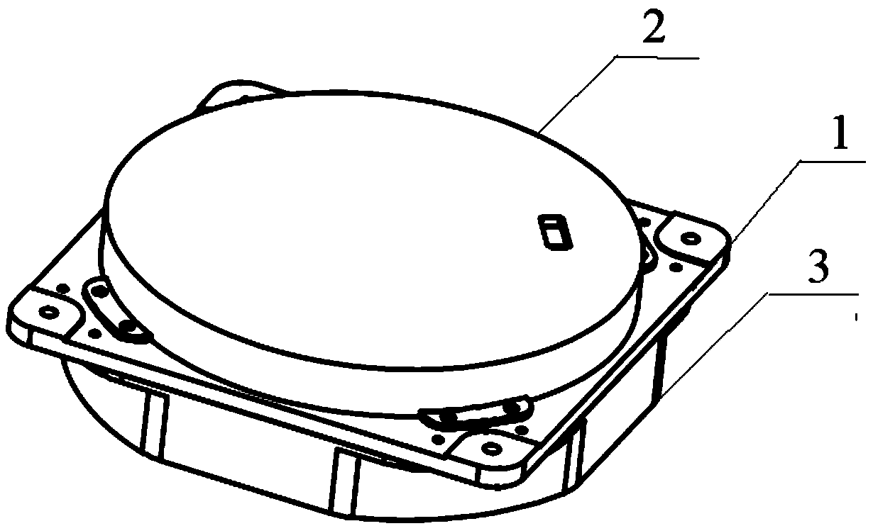
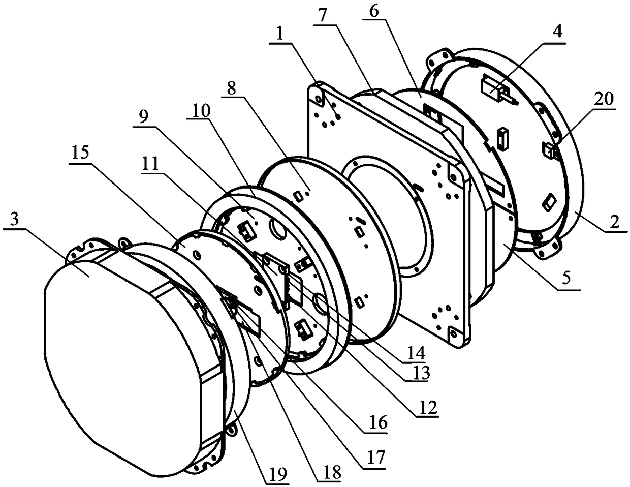
[0022] A high-precision fiber optic gyroscope, such as figure 1 with figure 2 As shown, the gyro is mainly composed of a housing, a base 1, a circuit board and a loop component.

[0023] Among them, the outer shell is composed of an upper shell 2 and a lower shell 3.

[0024] The circuit board includes two circuit boards: the main board 5 where the main board control circuit is located and the light source board 6 where the light source drive circuit is located.

[0025] The loop components include fiber ring base 9, 3000m polarization maintaining fiber ring 10, bait fiber press plate 11, wavelength division multiplexer 12, isolator 13, reflector 14, waveguide plate 15, coupler 16, temperature sensor 17 and Y waveguide 18; The fiber ring base 9 is a groove structure, and its outer side wall is provided with an annular mounting groove for placing the polarization maintaining fiber ring 10; the waveguide plate 15 is a groove structure.

[0026] The base 1 is located between the upper ...


PUM


Abstract

The invention relates to a high-precision optical fiber gyroscope, and belongs to the technical fields of optical fiber sensing and inertial navigation. The high-precision optical fiber gyroscope is characterized in that a circuit board comprises a main board and a light source board; a loop assembly comprises an optical fiber ring base, a polarization-maintaining optical fiber ring, a erbium-doped fiber press plate, a wavelength division multiplexer, an isolator, a reflective mirror, a wave guide plate, a coupler, a temperature sensor and a Y-shaped wave guide; the outside wall of the opticalfiber ring base is provided with an annular installation groove for accommodating the polarization-maintaining optical fiber ring; the base is positioned between an upper casing and a lower casing, and is used for separating a gyroscope body into an upper part and a lower part; the circuit board is positioned at the upper part of the gyroscope body, and the loop assembly is positioned at the lower part of the gyroscope body. The high-precision optical fiber gyroscope has the advantages that a heating device and a sensitive optical fiber ring are physically isolated by the base, so as to reduce the heat radiation interference of a transmission device to the light path part; a magnetic shielding technique is adopted for the optical fiber loop, so as to shield the geomagnetic interference and circuit electronic interference; a light source with stable wide bandwidth and high power of 1550 nm is built, so that the output wavelength is not sensitive to the temperature, and the relative intensity noise of the light source is inhibited.

Description

Technical field [0001] The invention relates to a high-precision optical fiber gyroscope, belonging to the technical field of optical fiber sensing and inertial navigation. Background technique [0002] The fiber optic gyroscope is based on the optical Sagnac effect to measure the angular rate movement of the carrier around the product's sensitive axis. It is a new generation of all solid-state inertial instruments developed in the 1970s. Compared with traditional electromechanical gyroscopes , Fiber optic gyroscope has received wide attention from all over the world due to its full solid state, no rotating parts, simple structure and high reliability. The development of domestic fiber optic gyroscopes started in the 1980s. At present, low- and medium-precision fiber optic gyroscopes have begun to be applied in engineering. However, their applications in strapdown systems and high-precision fiber optic gyroscopes in strategic navigation systems are further improving accuracy and ...

Claims


Application Information

Patent Timeline
Patent Type & Authority Applications(China)
IPC IPC(8): G01C19/72
CPCG01C19/721
Inventor 可伟代静胡文纲
Owner HEBEI HANGUANG HEAVY IND
Learn More