
Anti-collision radar target speed simulation device, system and method based on phase modulation

A technology of anti-collision radar and target speed, which is applied to radio wave measurement systems and instruments, can solve the problems of large hardware resource occupation, large hardware and software resources, and slow simulation speed, and achieve strong versatility and maintainability. The effect of reducing hardware resources and high phase modulation accuracy

Inactive Publication Date: 2021-01-22
CHINA ELECTRONIS TECH INSTR CO LTD
View PDF52 Cites 0 Cited by
  • Summary
  • Abstract
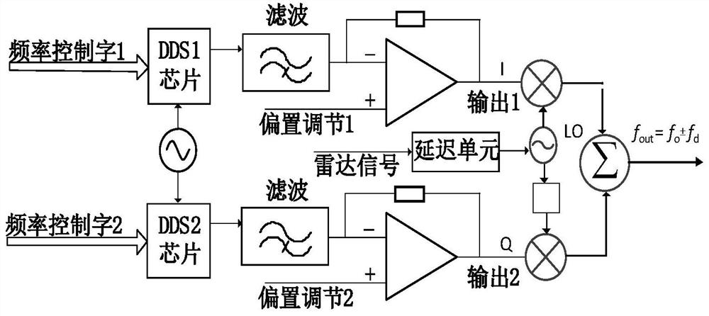
  • Description
  • Claims
  • Application Information

AI Technical Summary

Problems solved by technology

[0004] (1) The simulation speed is slow and the test efficiency is low;
[0005] The existing anti-collision radar target speed simulation method needs to send the signal emitted by the radar to the IQ modulator after a certain period of delay, the simulation speed is relatively slow, and the test efficiency is low for the radar production line test;
[0006] (2) The channel volume is large and the cost is high
[0007] The existing anti-collision radar target speed simulation device requires two DDS chips to generate two I and Q signals, which occupies more hardware and software resources. Sexual occasion application
[0008] To sum up, the existing methods and devices for simulating the speed of anti-collision radar targets require two-way Doppler frequency generating circuits, and there is local oscillator leakage through IQ mixing, which leads to the generation of false targets, and the simulated speed It is slow, which eventually leads to low test efficiency, and the hardware resources occupy a large volume and high cost. There is still a lack of effective technical solutions

Method used


Image

  • Anti-collision radar target speed simulation device, system and method based on phase modulation
  • Anti-collision radar target speed simulation device, system and method based on phase modulation
  • Anti-collision radar target speed simulation device, system and method based on phase modulation

Examples


Embodiment Construction

[0035] The present invention will be further described below in conjunction with the accompanying drawings and embodiments.

[0036] It should be pointed out that the following detailed description is exemplary and intended to provide further explanation to the present application. Unless defined otherwise, all technical and scientific terms used herein have the same meaning as commonly understood by one of ordinary skill in the art to which this application belongs.

[0037] It should be noted that the terminology used here is only for describing specific implementations, and is not intended to limit the exemplary implementations according to the present application. As used herein, unless the context clearly dictates otherwise, the singular is intended to include the plural, and it should also be understood that when the terms "comprising" and / or "comprising" are used in this specification, they mean There are features, steps, operations, means, components and / or combinatio...


PUM


Abstract

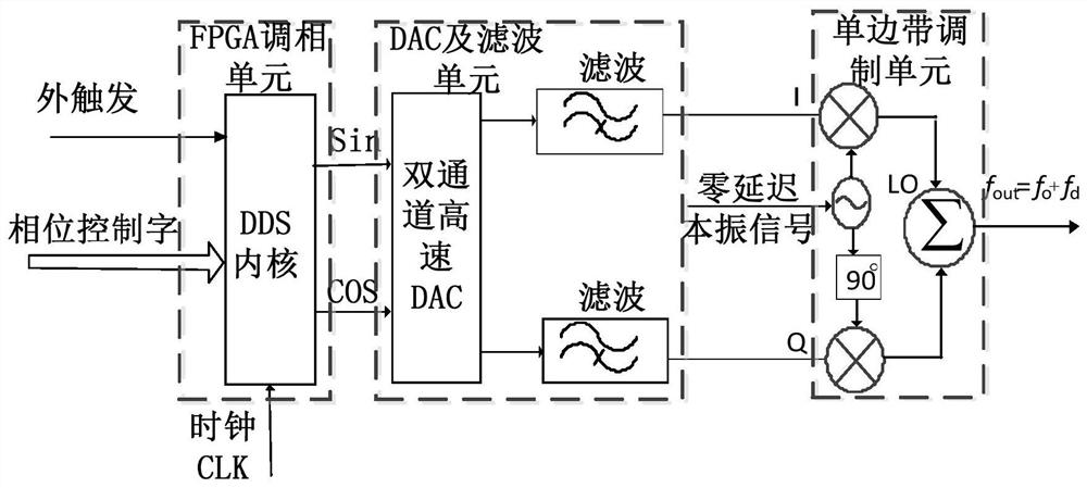
The invention discloses a device, system and method for simulating an anti-collision radar target speed based on a phase modulation mode. The device comprises a FPGA phase modulation unit, a DAC and filter unit and a single side band modulation unit, the FPGA phase modulation unit receives a phase control word sent by a host, generates sine and cosine two-way signals with different phases under the action of an external trigger signal, and sends the sine and cosine two-way signals to the DAC and filter unit; the DAC and filter unit convert the sine and cosine two-way digital signals into sineand cosine two-way analog signals, filter the two-way analog signals respectively, and send the filtered sine and cosine two-way analog signals to the single side band modulation unit; and the singleside band modulation unit receives a signal sent by an anti-collision radar as a zero-delay local oscillation signal, carries out IQ frequency mixing on the sine analog signal and the cosine analog signal and the zero-delay local oscillation signal respectively to obtain a final output frequency, and the final output frequency is sent to the input end of a transmitting channel of a simulator.

Description

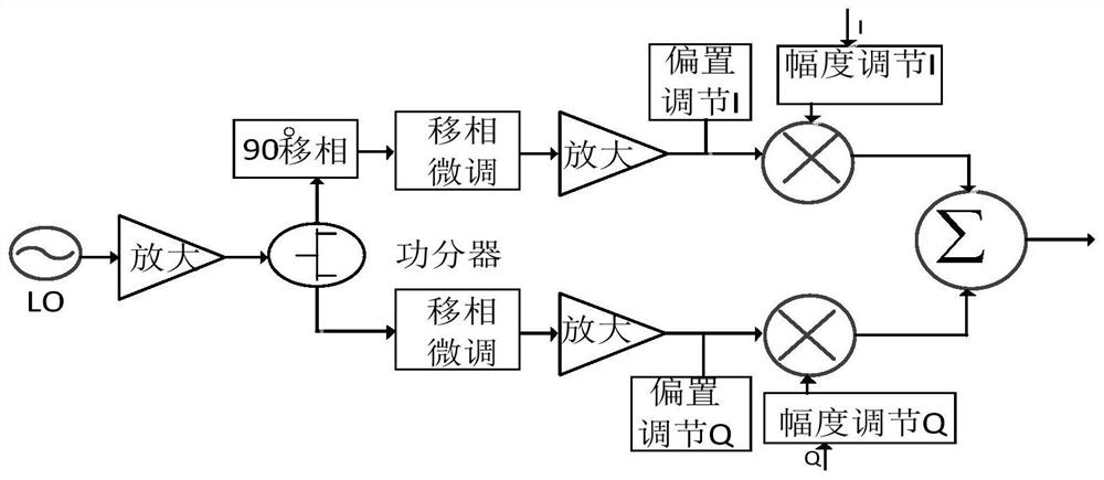
technical field [0001] The present disclosure relates to the technical field of radio frequency microwave testing, and in particular to an anti-collision radar target speed simulation device, system and simulation method based on phase modulation. Background technique [0002] The existing anti-collision radar target speed simulation method uses the Doppler frequency shift method. Firstly, according to the simulated speed and direction, two direction-controllable orthogonal signals are generated. The orthogonal signals are the same as the reflected signal of the target. After modulation and SSB filtering, it is transmitted through the transmitting antenna. After receiving the signal, the anti-collision radar performs internal processing to calculate the speed information. [0003] The above-mentioned simulation method needs to generate two high-precision Doppler frequency signals, and quadrature modulation is required on the channel. The local oscillator signal required by q...

Claims


Application Information

Patent Timeline
Patent Type & Authority Patents(China)
IPC IPC(8): G01S7/40
CPCG01S7/4052
Inventor 刘军智王盘伟唐建立
Owner CHINA ELECTRONIS TECH INSTR CO LTD
Learn More