Dynamic zero-pole tracing compensating circuit
A compensation circuit and zero-pole technology, applied in the field of compensation circuits, can solve the problems of high cost, complex structure, and many circuit components, and achieve the effects of simple structure, high robustness, and strong portability
- Summary
- Abstract
- Description
- Claims
- Application Information
AI Technical Summary
Problems solved by technology
Method used
Image
Examples
Embodiment 1
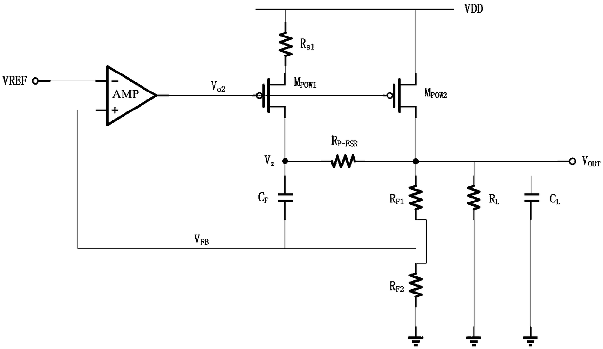
[0027] The invention provides a dynamic zero-pole tracking compensation circuit, which is used in a high-power LDO to provide compensation for the LDO loop and improve loop stability. The structure of the dynamic pole-zero tracking compensation circuit is as follows image 3 shown, including the main power tube M POW2 and from the power tube M POW1 , the main power tube M POW2 of the gate and the slave power transistor M POW1 gate interconnection, the slave power transistor M POW1 through resistor R s1 connected with the power supply VDD, the main power transistor M POW2 Connect directly to voltage VDD.
[0028] Specifically, the dynamic zero-pole tracking compensation circuit also includes a resistor R P-ESR , R L , R F1 , R F2 and capacitance C F 、C L , where the main power tube M POW2 The drain terminal passes through the resistor R F1 and resistor R F2 ground; the slave power tube M POW1 The drain terminal passes through the capacitor C F Connected to the ...
PUM
 Abstract
Description
Claims
Application Information
 - R&D
- Intellectual Property
- Life Sciences
- Materials
- Tech Scout
- Unparalleled Data Quality
- Higher Quality Content
- 60% Fewer Hallucinations
Browse by: Latest US Patents, China's latest patents, Technical Efficacy Thesaurus, Application Domain, Technology Topic, Popular Technical Reports.
© 2025 PatSnap. All rights reserved.Legal|Privacy policy|Modern Slavery Act Transparency Statement|Sitemap|About US| Contact US: help@patsnap.com


