Multilayer substrate integrated waveguide third-order filter power divider

A substrate-integrated waveguide and power divider technology, applied in waveguide devices, electrical components, connecting devices, etc., can solve the problems of increased circuit area, worsened insertion loss, and poor filtering performance, achieving high space utilization, Ease of processing and compact structure

Active Publication Date: 2019-03-12
SHANGHAI AEROSPACE COMP TECH INST
View PDF3 Cites 12 Cited by
  • Summary
  • Abstract
  • Description
  • Claims
  • Application Information

AI Technical Summary

Problems solved by technology

Since the emergence of substrate integrated waveguide technology, it has been widely used in the design of various bandpass filters. While improving its frequency selection characteristics by introducing multiple transmission zeros, the circuit will be caused by the existence of multiple resonators. Increase in area and deterioration of insertion loss in the passband
[0004] After searching the existing substrate-integrated waveguide filter power splitter, it was found that the patent "a multi-channel substrate-integrated waveguide filter power splitter" (patent number: CN 104091990 A) introduced a multi-layer substrate-based On-chip waveguide filter power divider, which generates filtering performance by cascading inductive windows, however, the filtering performance of this filter power divider is poor, there is no transmission zero point in the high and low stop bands, and the sideband suppression is relatively smooth

Method used


Image

  • Multilayer substrate integrated waveguide third-order filter power divider
  • Multilayer substrate integrated waveguide third-order filter power divider
  • Multilayer substrate integrated waveguide third-order filter power divider

Examples


Embodiment 1

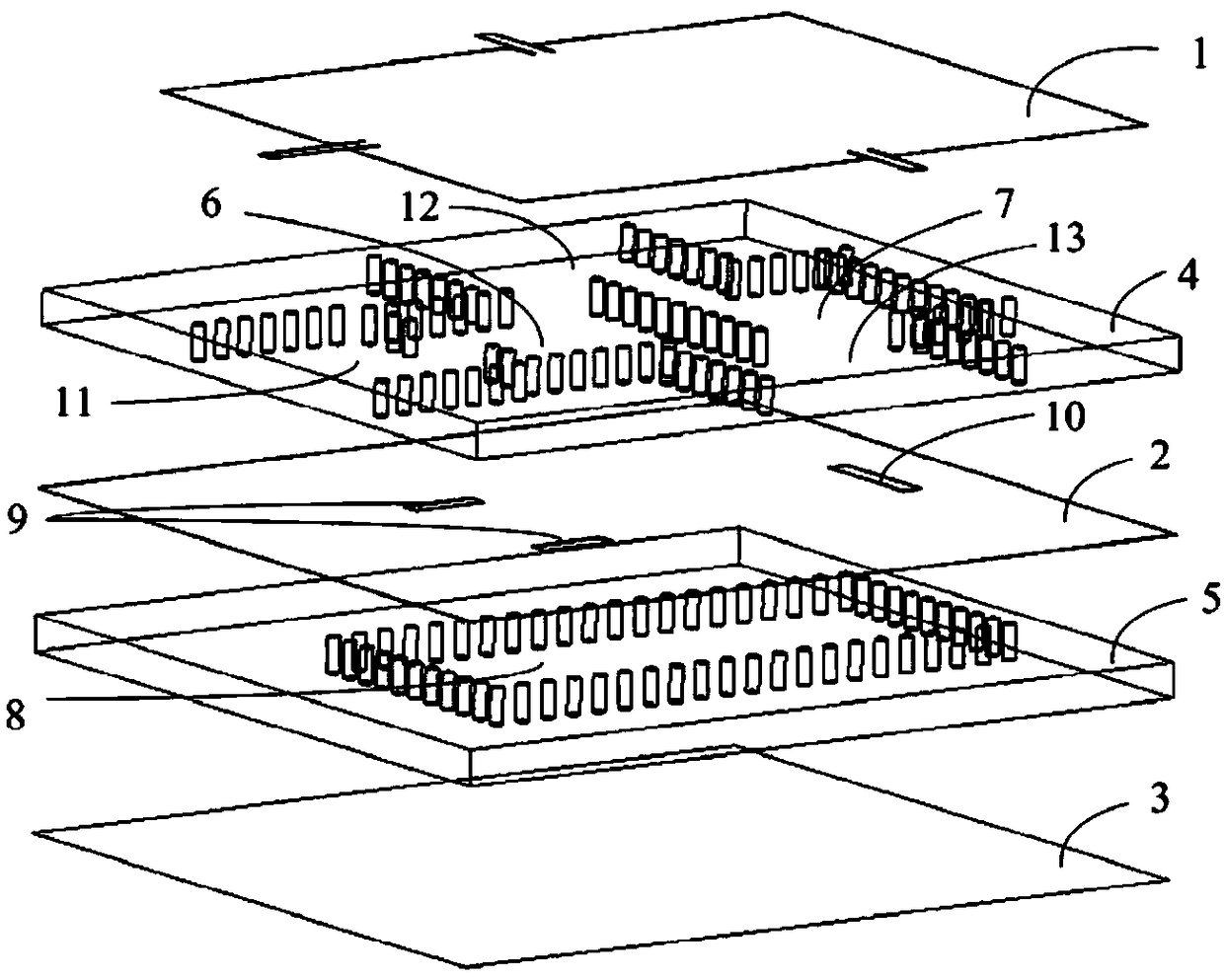
[0036] Please refer to figure 1 , a multi-layer substrate integrated waveguide third-order filter power divider, including a first metal layer 1, a second metal layer 2 and a third metal layer 3 stacked, the first metal layer 1 and the second metal layer 2 A first dielectric substrate 4 is arranged between them, and a second dielectric substrate 5 is arranged between the second metal layer 2 and the third metal layer 3;

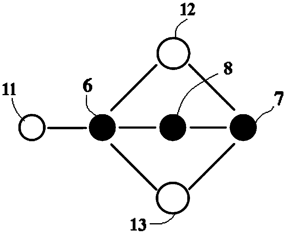
[0037] The first dielectric substrate 4 is provided with a first resonant cavity 6, a second resonant cavity 7, an input waveguide 11, a first output waveguide 12 and a second output waveguide 13;

[0038] The input waveguide 11 , the first output waveguide 12 and the second output waveguide 13 are converted from the substrate-integrated waveguide port of the first dielectric substrate 4 into the microstrip port output of the first metal layer 1 .

[0039] A third resonant cavity 8 is arranged on the second dielectric substrate 5;

[0040] The input wavegui...

Embodiment 2

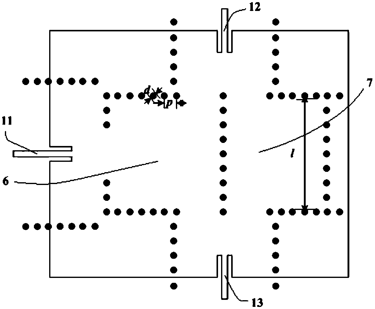
[0049] to combine figure 1 , please refer to Figure 3 ~ Figure 5 , the center frequency of the multi-order substrate integrated waveguide third-order filter power divider is controlled at 6.8GHz, the substrate material used in the first dielectric substrate 4 and the second dielectric substrate 5 is Rogers RO4350B, the dielectric constant is 3.48, and the thickness is 0.508 mm; the diameter d=0.7mm of all the metallized via holes on the first dielectric substrate and the second dielectric substrate, the pitch p=1.5mm; the width l=15mm of the first resonant cavity, the second resonant cavity and the third resonant cavity ;Length l of the first slot 9 1 =4.5mm, width w 1 =1.2mm; the length l of the second slot 10 2 =6.9mm, width w 2 = 1.2 mm.

[0050] Please refer to Figure 6 , it can be seen that the center frequency of the above multi-order substrate integrated waveguide third-order filter power divider is 6.77GHz, and the two output channels are equal in amplitude and...


PUM

PropertyMeasurementUnit
Center frequencyaaaaaaaaaa

Abstract

The invention discloses a multilayer substrate integrated waveguide third-order filter power divider, comprising a first metal layer, a second metal layer, a third metal layer, a first dielectric substrate and a second dielectric substrate, wherein the first dielectric substrate is provided with a first resonant cavity, a second resonant cavity, an input waveguide, a first output waveguide and a second output waveguide; the second dielectric substrate is provided with a third resonant cavity, the input waveguide excites the first resonant cavity, the first output waveguide and the second output waveguide simultaneously excite the first resonant cavity and the second resonant cavity, and the second metal layer is configured to adjust magnetic coupling coefficients of the first resonant cavity, the second resonant cavity, and the third resonant cavity to obtain two transmission zeros. The divider obtains additional transmission zeros by adjusting the electromagnetic coupling strength between the upper and lower cavities, and simultaneously integrates the characteristics of the power divider without changing the existing filter size, which has both the frequency selection characteristic and the power division performance.

Description

technical field [0001] The invention relates to the field of microwave passive devices, in particular to a multilayer substrate integrated waveguide third-order filter power splitter. Background technique [0002] In recent years, power splitters and filters, as mainstream passive devices, have received a lot of attention in communication systems. On the one hand, power splitters are mainly used for multi-channel power distribution and synthesis, especially in phased array radars, which consist of hundreds or thousands of antenna elements, requiring a large number of power splitters to realize; on the other hand, in order to ensure access to the system The frequency spectrum is clean, and frequency selection needs to be achieved through filters. However, it should be pointed out that using filters and power dividers to achieve frequency selection characteristics and power division performance respectively will increase the number of components, thereby affecting the cost an...

Claims


Application Information

Patent Timeline
IPC IPC(8): H01P5/12H01P1/20
CPCH01P1/2088H01P5/12
Inventor 沈玮张理正陈桂莲雒寒冰李振海张红英杨晶晶
Owner SHANGHAI AEROSPACE COMP TECH INST
Why Eureka
Try Eureka