Eureka AIR delivers breakthrough ideas for toughest innovation challenges, trusted by R&D personnel around the world.

Dual-redundancy general test system

A general-purpose testing and dual-redundancy technology, applied in transmission systems, digital transmission systems, electrical components, etc., can solve problems such as automatic interpretation, low requirements for independent excitation, no requirements for real-time acquisition and independent analysis, and difficulty in compatibility or expansion, etc. problems, to achieve the effect of high versatility, clear division of labor, and complete functions

Active Publication Date: 2019-03-12
PLA PEOPLES LIBERATION ARMY OF CHINA STRATEGIC SUPPORT FORCE AEROSPACE ENG UNIV
View PDF7 Cites 0 Cited by
  • Summary
  • Abstract
  • Description
  • Claims
  • Application Information

AI Technical Summary

Problems solved by technology

In the existing technology, the overall design of the test system is generally only aimed at completing a single function, and the real-time performance and reliability need to be improved. Some are only for analog signal or digital signal acquisition and testing, and some are only for signal acquisition without sending incentives.
Therefore, this type of test system is difficult to adapt to a variety of test environments with large data collection, complex incentive feedback loops, and high reliability and real-time requirements.
[0003] For example: test signal recorders generally only involve signal collection and recording functions, and do not have high requirements for automatic interpretation and independent excitation; digital control systems generally focus on the generation and control of excitation signals, and generally do not do real-time collection and independent analysis of feedback information. Requirements; such systems are often designed as dedicated systems for special needs, lacking the support of top-level design specifications and reserved expansion requirements. With the update and upgrade of test requirements, it is difficult to achieve compatibility or expansion for new requirements, which is not conducive to improving the system. Versatility, real-time and reliability

Method used


Image

  • Dual-redundancy general test system
  • Dual-redundancy general test system
  • Dual-redundancy general test system

Examples


Embodiment Construction

[0024] In order to make the object, technical solution and advantages of the present invention clearer, the present invention will be further described in detail below in combination with specific embodiments and with reference to the accompanying drawings. It should be understood that these descriptions are exemplary only, and are not intended to limit the scope of the present invention. Also, in the following description, descriptions of well-known structures and techniques are omitted to avoid unnecessarily obscuring the concept of the present invention.

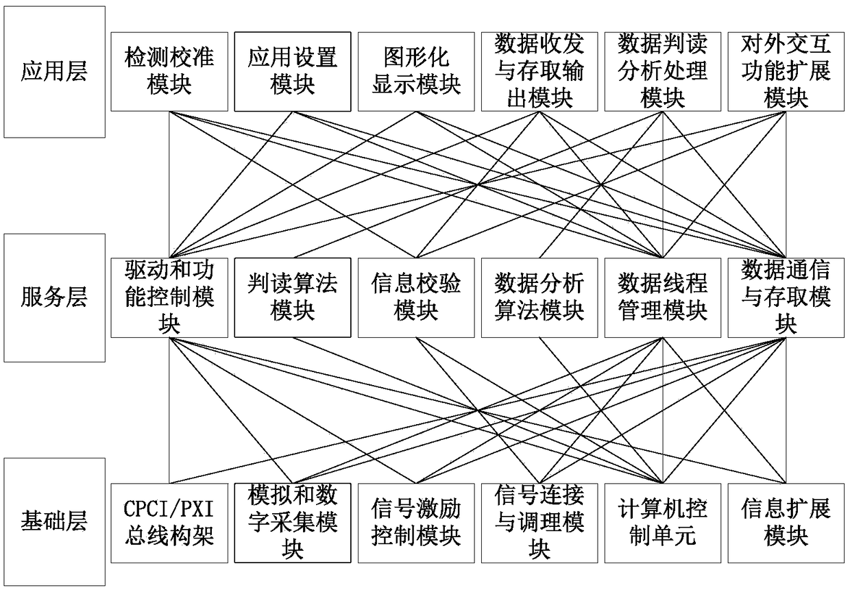
[0025] figure 1 It is a schematic structural diagram of a dual-redundant general test system according to an embodiment of the present invention.

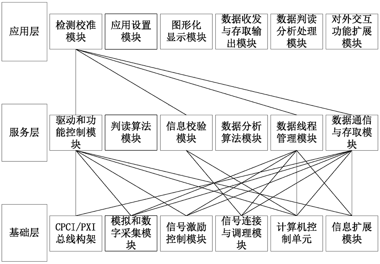
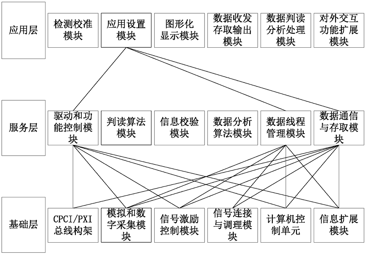
[0026] Such as figure 1 As shown, a dual-redundant general test system includes: base layer, service layer and application layer; the interrelationship between the modules of the base layer, service layer and application layer can be found in figure 1 , the interconnected m...


PUM


Abstract

The invention discloses a dual-redundancy general test system, which comprises a basic layer, a service layer and an application layer, wherein the basic layer is arranged on front-end equipment and provides a CPCI / PXI bus specification-based hardware support for the service layer, so as to connect a tested object with rear-end equipment; the service layer is arranged on the front-end equipment and the rear-end equipment and is used for providing a service function support for the application layer based on the basic layer; and the application layer is arranged on the front-end equipment and the rear-end equipment and is used for calling the basic layer based on the service layer to realize control of the basic layer and providing an interaction function with the front-end equipment or therear-end equipment for a user. The dual-redundancy general test system is applicable to different test systems and is relatively high in generality.

Description

technical field [0001] The invention belongs to the field of automatic distributed test systems, and in particular relates to a dual redundant general test system. Background technique [0002] An automated distributed test system is generally composed of front-end and back-end equipment, among which, the front-end equipment is controlled by the back-end equipment, implements data collection and processing, and sends the collected data to the back-end in real time; the back-end equipment receives data through the network and sends control commands to the front-end Device, to control the start and stop of the collection process of the front-end device. At present, there is no unified top-level design reference or specification for this type of test system, the user application, service support, and basic hardware levels are not clear, and the functional design is not perfect. In the existing technology, the overall design of the test system is generally only aimed at complet...

Claims


Application Information

Patent Timeline
IPC IPC(8): H04L12/26H04L1/22
CPCH04L1/22H04L43/50
Inventor 李岩蔡远文姚静波程龙解维奇辛朝军张宇杨甘霖
Owner PLA PEOPLES LIBERATION ARMY OF CHINA STRATEGIC SUPPORT FORCE AEROSPACE ENG UNIV
Why Eureka
Eureka Blog
Learn More