

Smoke and sewage separation pipe
A technology for separating pipes, flue gas and sewage, applied in separation methods, dispersed particle separation, chemical instruments and methods, etc., can solve problems such as low separation efficiency, and achieve the effects of improving separation efficiency, ensuring separation efficiency, and simple structure
Pending Publication Date: 2019-03-15
启明星宇节能科技股份有限公司
View PDF8 Cites 0 Cited by
- Summary
- Abstract
- Description
- Claims
- Application Information
AI Technical Summary
Problems solved by technology
[0007] For this reason, the present invention provides a flue gas sewage separation pipeline to overcome the problem of low separation efficiency in the prior art
Method used
View moreImage
Smart ImageViewing Examples

Examples
Embodiment 1
[0075] In this embodiment, the flue gas and sewage separation pipe of the present invention will be used to separate the flue gas mixture, wherein a 100-ton boiler is selected, the diameter of the conveying pipe 1 is 1800mm, the diameter of the sewage pipe is 200mm, and the specification of the wind shield is 200*300mm, and its right The side edge height is 200mm.
[0076] After the separation of the smoke-vapor mixture, it can be concluded that the flue-gas-sewage separation pipe of the present invention can effectively separate the smoke-gas-sewage mixture from the smoke-steam mixture.
Login to View More PUM
 Abstract
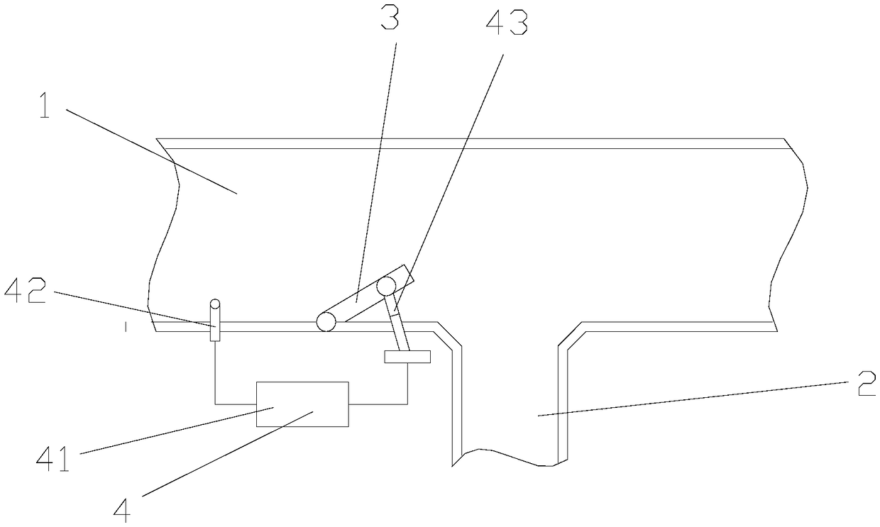
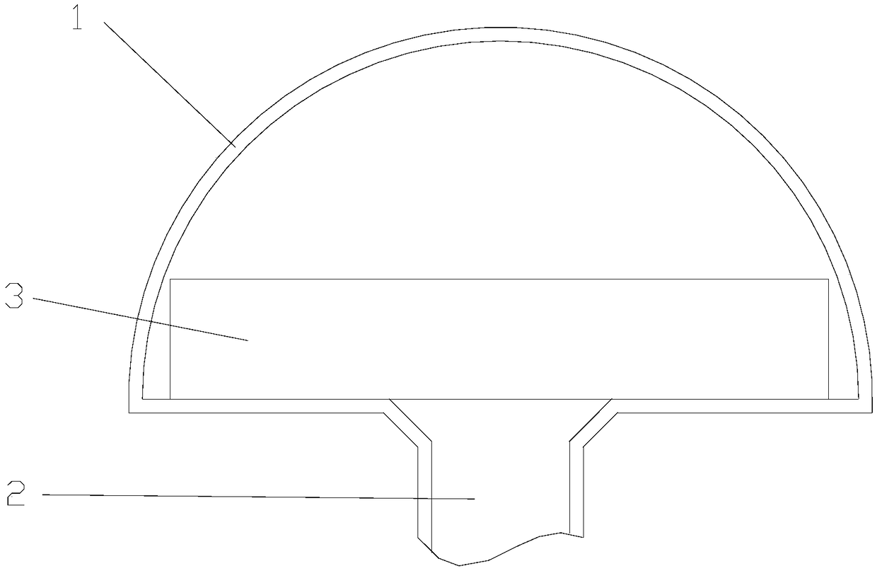
The invention relates to a smoke and sewage separation pipe. A shelter plate is arranged in the pipe to separate smoke from sewage in the pipe. The separation pipe comprises a conveying pipe for conveying a smoke-steam mixture, a sewage discharge pipe, the shelter plate and a control unit, wherein the sewage discharge pipe is arranged at the bottom of the conveying pipe and used for discharging sewage out of the conveying pipe; the shelter plate is arranged at the bottom of the conveying pipe and located at the upstream of the sewage discharging pipe, and is used for blocking sewage in the smoke-steam mixture and separating smoke from the sewage; the control unit is arranged on the outer wall of the conveying pipe and used for adjusting the angle of the shelter plate. The shelter plate isarranged in the conveying pipe, the sewage in the smoke-steam mixture is attached to the shelter plate and condensed into water drops, which are directly discharged through the sewage discharging pipe, so that the smoke and the sewage in the smoke-steam mixture can be quickly and efficiently separated; besides, the separation pipe has simple structure, and the manufacturing cost is reduced while separation efficiency is ensured.
Description
technical field [0001] The invention relates to the technical field of smoke-steam separation, in particular to a smoke-gas-sewage separation pipeline. Background technique [0002] For desulfurization and dust removal equipment, it is necessary to fully mix and contact the desulfurization agent or dedusting water with the flue gas through water during operation. When the operation is completed, it is necessary to separate the polluted water from the flue gas. It is difficult to separate and discharge the traditional method, because the flue gas and sewage are in the Under the action of the induced draft fan, it rotates and discharges in the direction of the flue outlet in the form of a mixture. In actual operation, in order to complete the separation of flue gas and polluted water, a polluted water discharge port is designed on the flue gas duct, but when the flue gas passes through the polluted water discharge port , The separation and removal efficiency is very low, and a...
Claims
Login to View More Application Information
Patent Timeline
 IPC IPC(8): B01D45/08
CPCB01D45/08
Inventor张久明
Owner启明星宇节能科技股份有限公司