Textile waste collection device of chemical fiber cloth

A textile waste and collection device technology, applied to chemical instruments and methods, cleaning methods using tools, cleaning methods using liquids, etc., can solve the problem of inability to collect large-scale waste, poor waste collection effect, and unreasonable settings and other issues, to achieve the effect of improving the use value, easy to take, and reasonable setting

Inactive Publication Date: 2019-03-15
长兴一盛纺织有限公司
View PDF5 Cites 5 Cited by
  • Summary
  • Abstract
  • Description
  • Claims
  • Application Information

AI Technical Summary

Problems solved by technology

[0004] The present invention provides a textile waste collection device for chemical fiber cloth, which can effectively solve the problem that the Chinese patent proposed in the above background technology discloses an authorized announcement number 108619832 CN A. into the interior of the device, which effectively avoids dust flying, has a simple structure, can quickly collect and wash textile waste, facilitates the recycling of textile waste, and has a good effect. However, the device uses manual methods to collect solid waste, and the setting Reasonable, when collecting waste on the production line, since the produced chemical fiber cloth has a lot of solid waste, manual collection is time-consuming and laborious, and the effect on waste collection is also poor. Secondly, the device is not installed to facilitate Moving base, which prevents large-scale waste collection

Method used


Image

  • Textile waste collection device of chemical fiber cloth
  • Textile waste collection device of chemical fiber cloth
  • Textile waste collection device of chemical fiber cloth

Examples


Embodiment

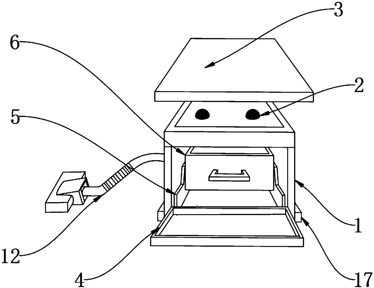
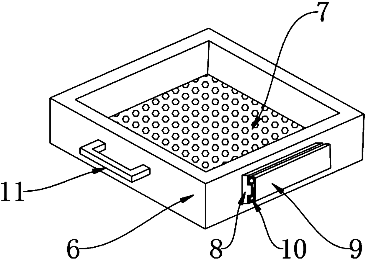
[0025] Example: such as Figure 1-5 As shown, the present invention provides a technical solution, a textile waste collection device for chemical fiber cloth, including a metal casing 1, in order to avoid rust and corrosion on the inner and outer surfaces of the metal casing 1, the inner and outer surfaces of the metal casing 1 are coated with Anti-rust paint, coarse filter screen 2 is installed on the top surface of the metal casing 1, a top cover 3 is installed on the top of the metal casing 1, a protective cover 4 is installed on one side of the metal casing 1, and an anti-rust filter is installed on the inner bottom of the metal casing 1. Grinding liner 5 and anti-wear liner 5 are equipped with a waste collection box 6 on one side, and a fine filter screen 7 is installed at the bottom of the waste collection box 6, and an inner fixed rail 8 is installed on one side of the waste collection box 6, and the inner fixed rail 8 One side is equipped with outer fixed rail 9, and s...


PUM


Abstract

The invention discloses a textile waste collection device of chemical fiber cloth, including a metal casing. A lining plate for prevent abrasion is arranged at the bottom end of the inner side of themetal casing. A waste collecting box is arranged on one side of the lining plate. A base is installed at the bottom end of the metal casing. The structure of the invention is scientific and reasonable, and the invention is safe and convenient to use. Through the function of a fine filter screen, filtration of collected waste in the waste collection box is performed, so as to classify the waste andincrease the value of waste. With the help of a metal plate, a pipeline, a connecting cover and a suction floor brush, the solid waste is sucked into the waste collecting box. The device avoids a manual method to collect the solid waste, saves time and labor, improves the efficiency of waste collection of the device, facilitates the movement of the whole device through the action of universal wheels, improves the convenience of the device, and is convenient for large-scale and large-area waste collection on the production line, and is reasonable in arrangement and comfortable in use.

Description

technical field [0001] The invention relates to the technical field of waste collection, in particular to a textile waste collection device for chemical fiber cloth. Background technique [0002] Chemical fiber cloth is a new type of clothing material developed in modern times. There are many types. Here it mainly refers to pure spinning, blended or interwoven fabrics processed from chemical fibers, that is to say, fabrics woven from purified fibers, excluding fabrics with natural fibers. Blended and interwoven fabrics, the characteristics of chemical fiber fabrics are determined by the characteristics of the chemical fibers that are woven into them. Chemical fiber fabrics will produce a lot of waste during the production process; [0003] The Chinese patent discloses an authorized announcement number 108619832 CN A. This patented technology uses a centrifugal exhaust fan to suck the dust-containing gas from the outside into the device, effectively avoiding the dust from fly...

Claims


Application Information

Patent Timeline
Patent Type & Authority Applications(China)
IPC IPC(8): B08B5/04B08B1/00B08B13/00B07B1/04B08B3/10B08B3/08
CPCB07B1/04B08B1/002B08B3/08B08B3/102B08B5/04B08B13/00
Inventor 张辰罗冬英
Owner 长兴一盛纺织有限公司
Why Eureka
Try Eureka