Floating type bottom plate for vacuum casting steel ingot and using method thereof

A vacuum casting and floating technology, applied in ingot casting workshops, manufacturing tools, casting workshops, etc., can solve the problems of reducing the service life of the ingot body iron mold, the large size of the large ingot body iron mold, and the unfavorable development of enterprises. The effect of capital consumption, reducing floor space, improving pouring range and efficiency

Pending Publication Date: 2019-03-15
武汉重工铸锻有限责任公司
View PDF0 Cites 0 Cited by
  • Summary
  • Abstract
  • Description
  • Claims
  • Application Information

AI Technical Summary

Problems solved by technology

The large ingot body iron mold has a large size and high casting cost. In order to meet the production demand, it is necessary to purchase a dedicated ingot body iron mold for each tonnage of steel ingot
Some tonnage steel ingots have less demand, and the special pouring accessories will be left idle for a long time, which reduces the service life of the ingot iron mold and causes a lot of money waste, which is not conducive to enterprise development.

Method used


Image

  • Floating type bottom plate for vacuum casting steel ingot and using method thereof
  • Floating type bottom plate for vacuum casting steel ingot and using method thereof
  • Floating type bottom plate for vacuum casting steel ingot and using method thereof

Examples


Embodiment Construction

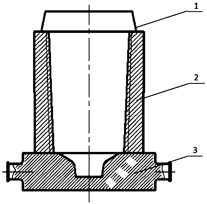
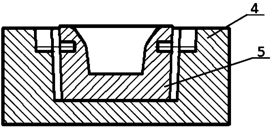
[0025] refer to figure 2 , floating chassis for vacuum casting steel ingots: there are 4 outer seats and 5 inner seats. There is an outer seat and an inner platform, the diameter of the outer seat is consistent with the diameter of the fixed chassis, and the opening diameter of the inner platform is 370±5mm smaller than that of the fixed chassis.

[0026] There is a gap of 75±2mm between the inner platform and the outer seat, the inner platform and the outer seat are wider at the top and narrower at the bottom, with a taper of 7.6°±0.2°, and the inner platform is 20±2mm higher than the inner cavity of the outer seat; There are pads 3 that can increase the different heights of the inner platform, and there are U-shaped grooves with a length of 150mm, a width of 175mm, and a depth of 170mm+R75mm along both sides on the outer seat inner cavity.

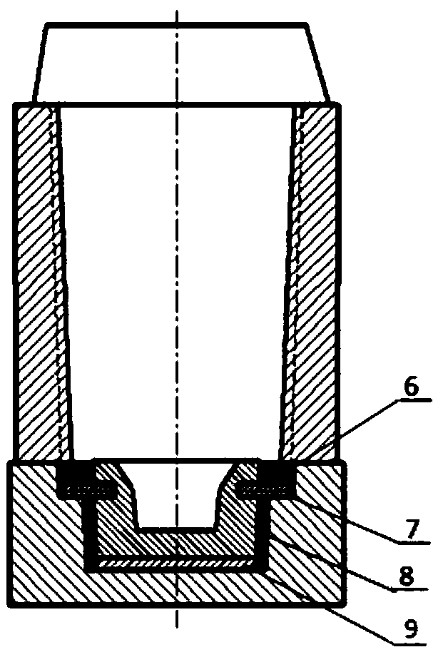
[0027] There are multiple layers of pin holes on the inner platform, and there is a 60° misalignment between the pin holes in plane v...


PUM


Abstract

The invention relates to a floating type bottom plate for vacuum casting steel ingots and a using method thereof. The bottom plate is provided with an outer base and an inner table, wherein a gap is formed between the inner table and the outer base, for the inner table and the outer base, the upper parts are wide, and the lower parts are narrow; the inner table is higher than an inner cavity of the outer base, cushion blocks capable of increasing the height of the inner table by different degrees are arranged in the inner cavity of the outer base, and a U-shaped groove is formed in the inner cavity of the outer base; and a plurality of layers of inserting pin holes are formed in the inner table, and a U-shaped clamping groove which allows inserting pins to be embedded is formed in the outer base. During use, the outer base is positioned, and the steel ingots with the tonnage in the application range are directly assembled; for the steel ingots which requires the inner table to be lifted, assembly is carried out after the cushion blocks are placed at the bottom of the outer base; the inner table is placed, the inserting pins are inserted into the inserting pin holes; scrap iron is added to the inserting pins, and filling materials are added under the inserting pins; an ingot body iron mold is placed on the inner table and the outer base, and an inner cavity of the ingot body iron mold is ensured to be concentric with an inner cavity of the inner table; and the steel ingots are poured in a vacuum mode. The floating type bottom plate is suitable for vacuum casting of various large-tonnage steel ingots, and switching is convenient; the use is safe, and the inserting pins can also be used as lifting lugs; and the number of the ingot body iron molds can be reduced, the utilization efficiency of the steel ingots is improved, the occupied area is reduced, and the fund consumption is reduced.

Description

technical field [0001] The invention relates to a floating chassis for vacuum casting steel ingots and a using method thereof. Background technique [0002] With the continuous development of equipment in nuclear power generation, aerospace, shipbuilding, petrochemical, machinery, and metallurgical industries, the demand for large forgings is increasing. At the same time, with the increasingly fierce market competition, how to reduce production costs and create greater benefits is an effective way for enterprises to survive and develop. The floating bottom plate for vacuum casting steel ingot designed by the present invention adjusts the height of the ingot body by adjusting the height of the inner platform, so as to achieve the purpose of tonnage, increase the ingot body ratio of the steel ingot, reduce the types of iron molds for the ingot body, and make the cast steel ingot ingot shape more accurate. Flexible to achieve the purpose of saving money and reducing costs. ...

Claims


Application Information

Patent Timeline
IPC IPC(8): B22D7/12B22D9/00B22D27/15
CPCB22D7/12B22D9/003B22D27/15
Inventor 曾文锋黄丽秋黄永强张庆坤来坤领唐继周郭志刚陈雄王强王高宏
Owner 武汉重工铸锻有限责任公司
Why Eureka
Try Eureka