
Tool grinder

A technology for tool grinding machines and workpieces, which is applied in the direction of grinding machines, manufacturing tools, and parts of grinding machine tools, etc. It can solve the problems of low grinding efficiency and inability to automatically replace grinding wheel sets, etc., achieve high grinding efficiency, improve grinding accuracy, The effect of detecting convenience

Pending Publication Date: 2019-03-15
TAIZHOU BEIPING MASCH TOOL CO LTD
View PDF11 Cites 2 Cited by
  • Summary
  • Abstract
  • Description
  • Claims
  • Application Information

AI Technical Summary

Problems solved by technology

However, this CNC tool grinder only has one grinding wheel set, so the grinding wheel set cannot be replaced automatically, and only one grinding process can be performed, which makes the grinding efficiency low

Method used


Image

  • Tool grinder
  • Tool grinder
  • Tool grinder

Examples


Embodiment Construction

[0029] The following are specific embodiments of the present invention and in conjunction with the accompanying drawings, the technical solutions of the present invention are further described, but the present invention is not limited to these embodiments.

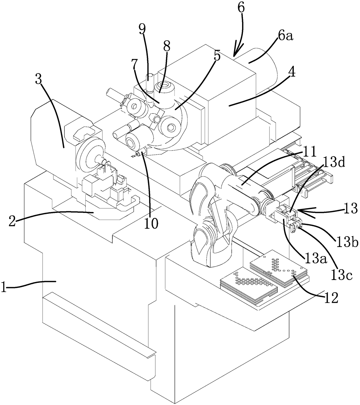
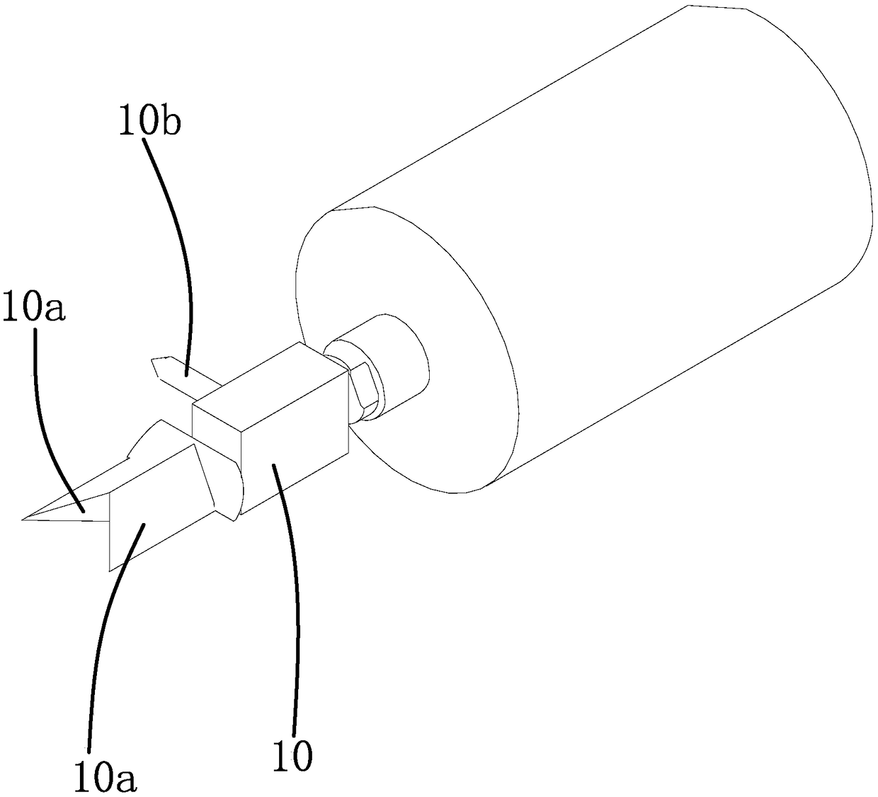
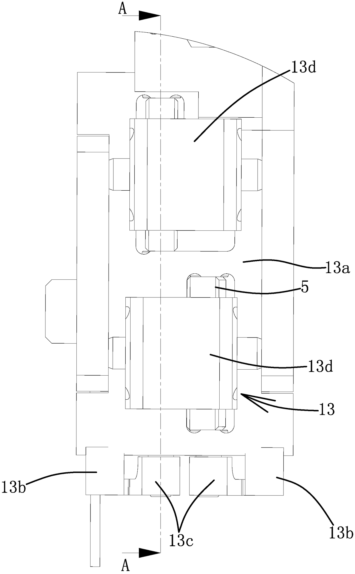
[0030] Such as Figures 1 to 4 As shown, a tool grinder includes a frame 1, a workbench 2 and a lifting mechanism that drives the workbench 2 to reciprocate on the frame 1, and a floating chuck 3 capable of clamping a workpiece is provided on the workbench 2 and drives The motor that floating chuck 3 rotates. The specific structure of the floating chuck 3 can refer to the floating chuck 3 (201710231797X) and the adjustable chuck (2017203728698) before this application.

[0031]One side of the workbench 2 is provided with a mounting frame 4, the mounting frame 4 can move horizontally and laterally and horizontally and longitudinally relative to the workbench 2, and the mounting frame 4 is provided with a rotating disk 5 an...


PUM


Abstract

The invention provides a tool grinder and belongs to the technical field of machinery. By means of the tool grinder, the problem that an existing tool grinder only can carry out one-time grinding machining, and the grinding efficiency is relatively low is solved. The tool grinder comprises a rack. The rack is provided with a workbench and a lifting mechanism which drives the workbench to ascend and descend back and forth. The workbench is provided with a floating clamp which can clamp a workpiece and a motor which can drive the floating clamp to rotate. One side of the workbench is provided with an installation frame, the installation frame can horizontally and transversely move and horizontally and longitudinally move relative to the workbench, and the installation frame is provided witha rotating disk and a rotating mechanism which drives the rotating disk to rotate. The rotating disk is evenly provided with a plurality of motors. Rotating shafts of the motors are provided with grinding wheels. The tool grinder has the advantages that the grinding efficiency is relatively high and the tool grinder works stably and reliably.

Description

technical field [0001] The invention belongs to the technical field of machinery, and relates to a fastener, in particular to a tool grinder. Background technique [0002] CNC tool grinding machines are more and more widely used in mechanical manufacturing and processing. Since the workpieces to be processed by tool grinding machines are generally tools with relatively complex shapes, the materials have high hardness and high precision requirements. Therefore, a lot of questions have been put forward for the structure of the machine tool and the design of the transmission system, the degree of automation of processing, and the stability of processing. high demands. [0003] The degree of automation, the rationality of the structure and transmission system, and the grinding precision of the CNC tool grinding machine in the prior art cannot meet the processing requirements. For example, automatic loading and unloading cannot be realized yet; workpiece clamping cannot be full...

Claims


Application Information

Patent Timeline
Patent Type & Authority Applications(China)
IPC IPC(8): B24B19/00B24B27/00B24B41/00B24B41/04B24B41/06B24B47/12B24B47/20B24B47/22B24B49/00B24B55/02
CPCB24B19/00B24B27/0076B24B41/005B24B41/04B24B41/06B24B47/12B24B47/20B24B47/22B24B49/00B24B55/02
Inventor 虞荣华
Owner TAIZHOU BEIPING MASCH TOOL CO LTD
Learn More