An anti-alarm heat exchange system

The technology of a heat exchange system and a heat exchange device is applied in the field of anti-alarm heat exchange systems, which can solve the problems of cumbersome operation, time-consuming and difficult to control, and achieve simple and convenient operation, improve work efficiency, and reduce operation difficulty and workload. Effect

Active Publication Date: 2021-03-12
SHANGHAI HUALI MICROELECTRONICS CORP
View PDF5 Cites 0 Cited by
  • Summary
  • Abstract
  • Description
  • Claims
  • Application Information

AI Technical Summary

Problems solved by technology

However, this solution is cumbersome to operate, takes a long time, and is not easy to control, which makes the heat exchange device alarm

Method used


Image

  • An anti-alarm heat exchange system
  • An anti-alarm heat exchange system
  • An anti-alarm heat exchange system

Examples


Embodiment 1

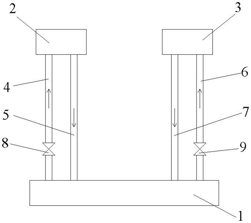
[0033] An exemplary embodiment of the present invention, such as figure 2 As shown, an anti-alarm heat exchange system includes a heat exchange device 1, a first cavity 2, and a second cavity 3, and the heat exchange device 1 communicates with the first cavity 2 and the second cavity 3 respectively to form a Corresponding cooling water circulation circuit.

[0034] The first cavity 2 forms a first circulation loop with the heat exchange device 1 through the first water inlet pipeline 4 and the first water outlet pipeline 5, and the cooling water in the heat exchange device 1 enters the first cavity through the first water inlet pipeline 4 2, the cooling water in the first cavity 2 enters the heat exchange device 1 through the first outlet pipe 5.

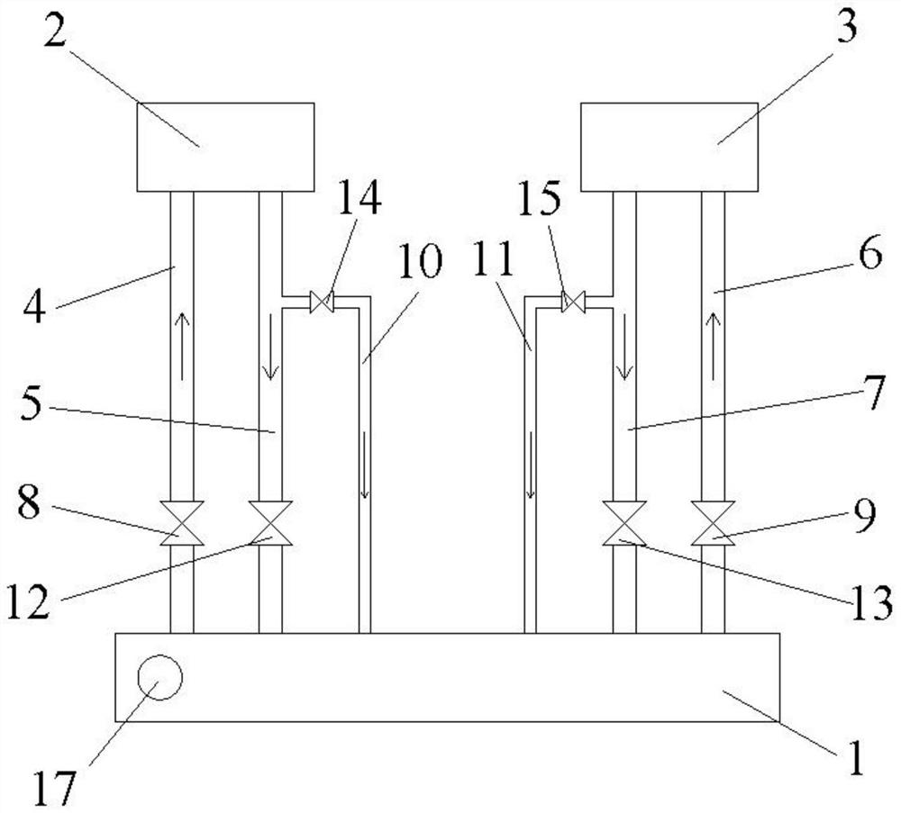
[0035] The first cavity 2 is also communicated with the heat exchange device 1 through the first water outlet branch pipeline 10, the first end of the first water outlet branch pipeline 10 communicates with the first water outlet ...

Embodiment 2

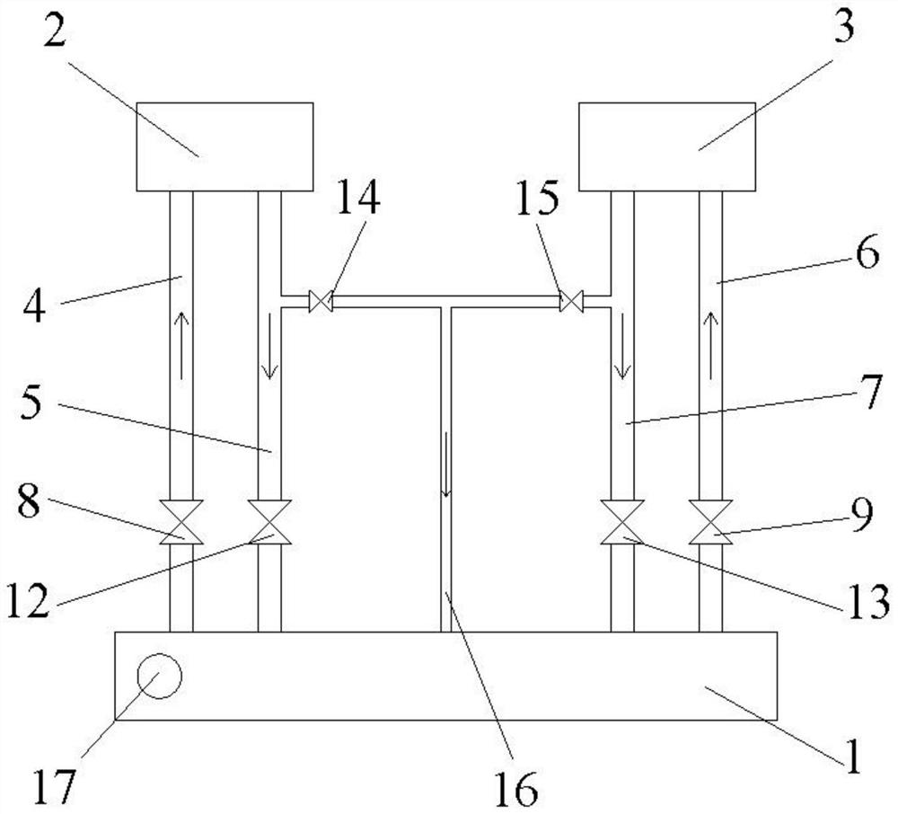
[0050] A preferred embodiment of the present invention, the difference between this embodiment and Embodiment 1 is that the first water outlet branch pipeline 10 communicates with the second water outlet branch pipeline 11 to form a third water outlet pipeline 16 .

[0051] An anti-alarm heat exchange system, including a heat exchange device 1, a first cavity 2, a second cavity 3, a first water inlet pipeline 4, a first water outlet pipeline 5, a second water inlet pipeline 6, a second water inlet pipeline The water outlet pipeline 7, the first valve 8, the second valve 9, the third valve 12 and the fourth valve 13, and the heat exchange device 1 communicate with the first cavity 2 and the second cavity 3 respectively to form a corresponding cooling water circulation loop .

[0052] Among them, the heat exchange device 1, the first cavity 2, the second cavity 3, the first water inlet pipeline 4, the first water outlet pipeline 5, the second water inlet pipeline 6, the second w...


PUM


Abstract

The invention relates to an anti-alarm heat exchange system, comprising a heat exchange device, a first cavity, a second cavity, a first water inlet pipeline, a first water outlet pipeline, a second water inlet pipeline, and a second water outlet pipeline , the first water outlet branch pipeline, the first water outlet branch pipeline communicates with the heat exchange device for heat exchange with the first water outlet pipeline respectively; the second water outlet branch pipeline, the second water outlet branch pipeline communicates with the second water outlet pipeline respectively The water pipeline communicates with the heat exchange device; the inner diameter of the first water outlet branch pipeline is smaller than the inner diameter of the first water outlet pipeline, and the inner diameter of the second water outlet branch pipeline is smaller than the inner diameter of the second water outlet pipeline. The advantage is that by setting the small-caliber outlet branch pipeline, the low-temperature cooling water in the cavity can slowly enter the heat exchange device after the PM process is completed in the cavity, thereby preventing the low-temperature cooling water from entering the heat exchange device in a short period of time. , so that the cooling water in the heat exchange device does not drop in temperature significantly, and an alarm condition is avoided.

Description

technical field [0001] The invention relates to the technical field of semiconductor manufacturing, in particular to an alarm-proof heat exchange system. Background technique [0002] In the physical vapor deposition (Physical Vapor Deposition, PVD) machine, the two TxZ chambers share the same heat exchange device, which provides cooling water at 65°C for the two chambers. The system is as follows figure 1 shown. When any one of the chambers undergoes preventive maintenance (Preventive Maintenance, PM), it is necessary to disconnect the cooling water circulation loop between the heat exchange device and the chamber. During the PM process, the cooling water at 65°C stays in the cavity for too long, causing the temperature of the cooling water to drop to room temperature. After the PM is completed, reconnect the cooling water circulation loop between the cavity and the heat exchange device. At this time The low-temperature cooling water in the cavity enters the heat exchange...

Claims


Application Information

Patent Timeline
Patent Type & Authority Patents(China)
IPC IPC(8): C23C14/56F28F27/00
CPCC23C14/56F28F27/00
Inventor 朱亮柳小敏
Owner SHANGHAI HUALI MICROELECTRONICS CORP
Why Eureka
Try Eureka