A plugging plate and a plugging device for a grouting sleeve communicating chamber

A technology for grouting sleeves and plugging plates, which is applied to buildings, building reinforcements, building components, etc., can solve the problems of inability to ensure the uniformity of grouting, delaying the construction progress, and long construction time, so as to reduce the hidden dangers of grouting quality, Quick installation and high construction efficiency

Active Publication Date: 2021-02-05
筑友智造建设科技集团有限公司
View PDF4 Cites 0 Cited by
  • Summary
  • Abstract
  • Description
  • Claims
  • Application Information

AI Technical Summary

Problems solved by technology

The use of sitting grout to seal the edge of the upper and lower prefabricated component connecting warehouses has the following problems: 1. After hoisting and positioning the upper prefabricated component, it is necessary to wait for more than 12 hours to ensure that the slurry for the sitting grout solidifies, so the construction time is longer; 2. Due to the upper prefabricated component It cannot be put down completely at a uniform speed and smoothly, causing the bottom side of the upper prefabricated component to often disperse the sitting grout on the top side of the lower prefabricated component, which requires grouting in the later stage; 3. Since the uniformity of the sitting grout cannot be guaranteed, the weak parts are grouted in the sleeve When grouting, it is easy to crack and leak after being under pressure; 4. Due to the high pressure of the grouting sleeve during grouting, the grouting pressure is slightly higher, and the grouting position will burst, resulting in the need to suspend the grouting. Refill the grout at the sitting position and wait for it to solidify, delaying the construction progress

Method used


Image

  • A plugging plate and a plugging device for a grouting sleeve communicating chamber
  • A plugging plate and a plugging device for a grouting sleeve communicating chamber
  • A plugging plate and a plugging device for a grouting sleeve communicating chamber

Examples


Embodiment 1

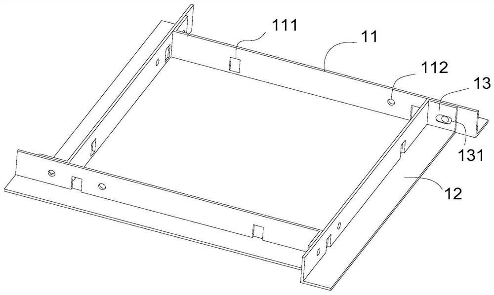
[0030]Reference schematicfigure 1 In this embodiment, the blocking plate includes a baffle 1. The baffle 1 includes two vertical vertical plates 11, a horizontal plate 12, and a fixing plate 13. The vertical plate 11 is provided with a fixing hole 111 and a through hole 112, and the fixing plate 13 A card hole 131 is opened on the top. The baffle 1 is respectively arranged on the periphery of the prefabricated member, wherein the fixing plate 13 and the vertical plate 11 of the adjacent baffle 1 are pressed against each other, and the clip (not shown in the figure) is passed through the through hole 112 and the blocking on the vertical plate 11 The card holes 131 on the board fasten adjacent baffles 1 together. Since the prefabricated component in this embodiment is a prefabricated column, the four baffles 1 surround a rectangle.

[0031]Continue to see the schematicfigure 1 In actual production, the cross-sectional dimension difference of prefabricated columns of different specificati...

Embodiment 2

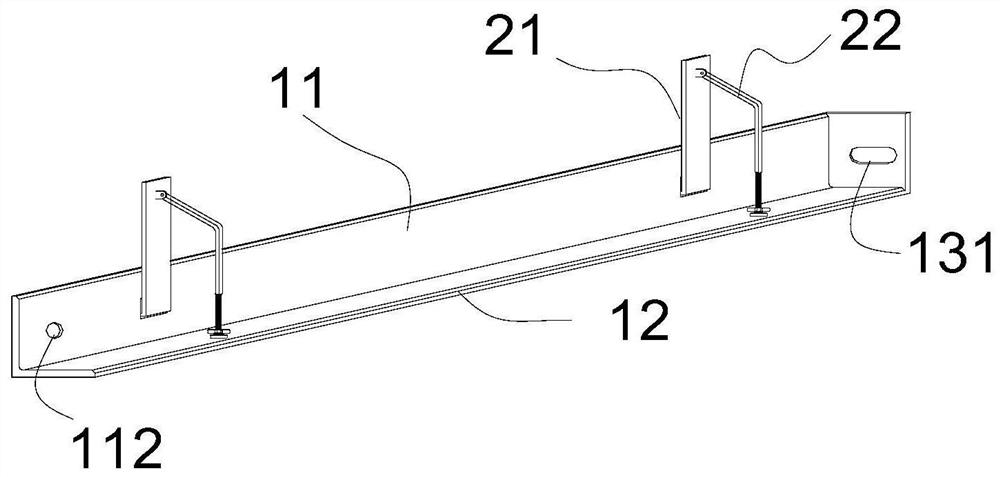
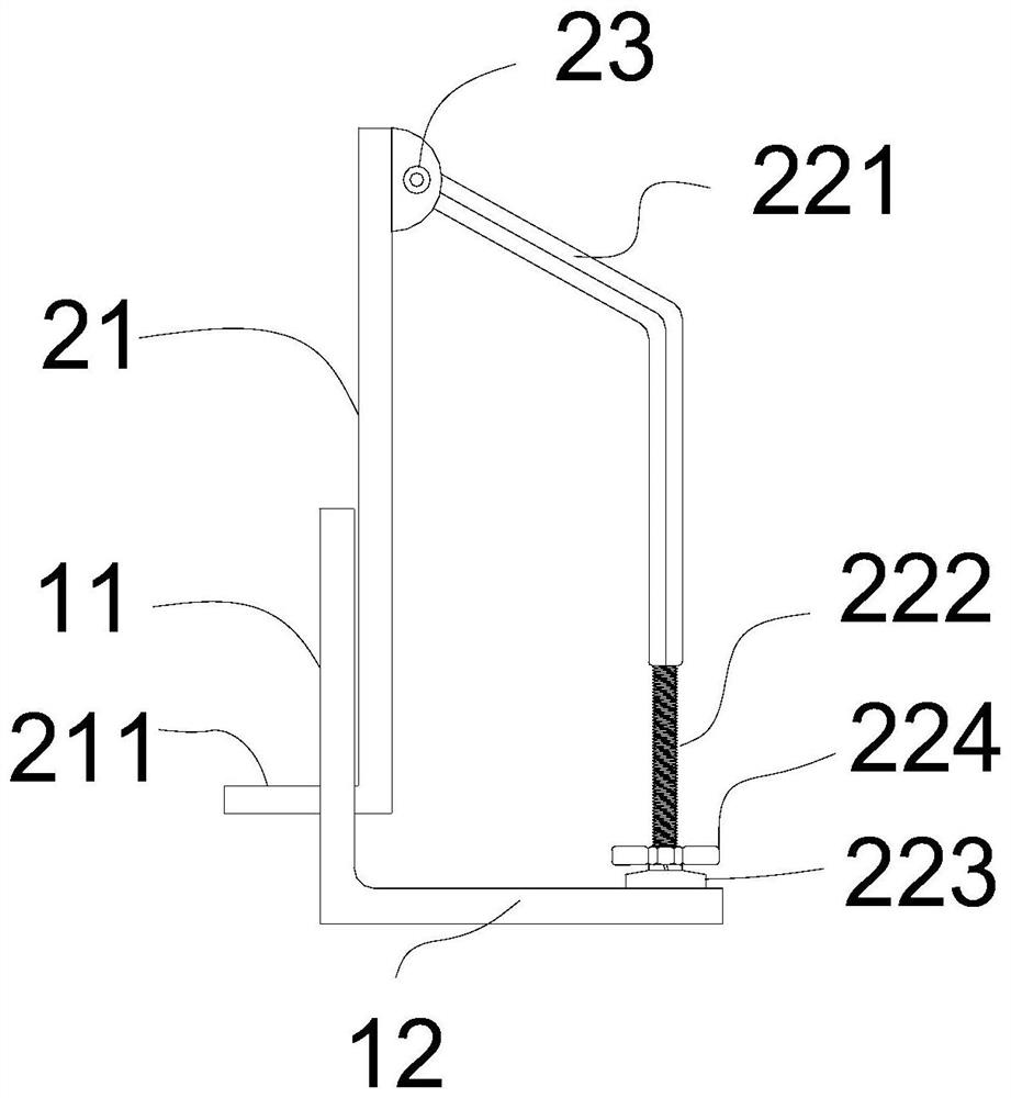
[0033]See schematicfigure 2 with3In this embodiment, the blocking plate includes a baffle 1 and a vertical fastening assembly 2, and the vertical fastening assembly 2 includes an L-shaped support plate 21 and an adjusting rod 22, which are hingedly connected by a hinge 23. The end of the L-shaped pallet 21 is provided with a fixing portion 211, and in this embodiment, the fixing portion 211 and the L-shaped pallet 21 are perpendicular to each other. The adjusting rod 22 includes an outer rod 221 and an inner rod 222. The outer rod 221 is provided with an inner thread, the inner rod 222 is provided with an outer thread, and the outer rod 221 is sleeved on the inner rod 222 and connected by a thread structure. When the outer rod 221 or the inner rod 222 is rotated, the overall length of the adjusting rod 22 is adjusted. The fixing portion 211 of the L-shaped pallet 21 extends into the fixing hole 111 of the vertical plate 11, the end of the inner rod 222 is pressed on the horizontal p...

Embodiment 3

[0037]In this embodiment, a plugging device for connecting a grouting sleeve to a bin is introduced, which is formed by a combination of four plugging plates shown in Embodiment 2. The plugging plate includes a plugging plate 1 and a vertical fastening component 2. In other embodiments, the number of blocking plates can be selected for combination according to specific conditions. For example, a circular prefabricated column, the blocking plate 1 is set in a shape that matches the outer circumference of the circular prefabricated column, and the bottom side of a circular prefabricated column Only 2 matching blocking plates can be provided.

[0038]SeeFigure 4 As shown, the use method and working principle of the plugging device of this embodiment are introduced:

[0039]The upper component is a prefabricated column 3, the internal anchoring column reinforcement 31, and the end of the column reinforcement 31 is provided with a grouting sleeve 32. The lower member is the foundation 4, and t...


PUM


Abstract

The invention discloses a plugging plate of a grouting sleeve communicating silo, comprising a baffle plate and a vertical fastening component. The baffle plate includes a vertical plate and a horizontal plate arranged perpendicular to each other, and the vertical plate is provided with a fixing hole; the vertical fastening The assembly includes an L-shaped support plate and an adjustment rod, the lower part of the L-shaped support plate is arranged opposite to the inner side of the vertical plate, and the end of the lower part of the L-shaped support plate is inserted into the fixing hole, and the first end of the adjustment rod is connected to the upper part of the L-shaped support plate. The hinge joint and the second end are pressed and arranged on the inner side surface of the horizontal plate. The invention also provides a plugging device for a grouting sleeve communicating bin, which is formed by combining more than two plugging plates, and the ends of the adjacent plugging plates are compressed and fixed by clips. The plugging device of this scheme is arranged at the joints of the upper and lower prefabricated components to form a closed empty warehouse to ensure that the grouting sleeve does not leak during the grouting process; it reduces the hidden danger of grouting quality; the installation is fast and convenient, no grouting is required during construction, and the construction efficiency is high. , can be used for multiple turnovers; fine-tuning range is reserved in both the horizontal and vertical directions, which is highly practical.

Description

Technical field[0001]The invention belongs to the technical field of building construction. Specifically, the invention relates to a plugging plate and a plugging device of a grouting sleeve communicating with a warehouse.Background technique[0002]In the construction of prefabricated buildings, the vertical prefabricated components can be connected to the upper and lower prefabricated components through the embedded sleeve grouting. During production, the upper prefabricated components, such as the shear wall and the bottom side of the prefabricated columns, are embedded with grouting sleeves. The top of the grouting sleeve is anchored with the stressed steel bars of the upper prefabricated components, and the bottom end is provided with a steel connection port; the top of the lower prefabricated components The stressed steel bars extend from the side. During construction, the stressed steel bars of the lower prefabricated component extend into the steel bar connection at the bottom...

Claims


Application Information

Patent Timeline
Patent Type & Authority Patents(China)
IPC IPC(8): E04C5/16
CPCE04C5/165
Inventor 肖阿林唐雄
Owner 筑友智造建设科技集团有限公司
Why Eureka
Try Eureka