Test device and test method for automatic chemical shutdown system

A shutdown system and automatic chemistry technology, applied in the direction of reactor, nuclear reactor monitoring, greenhouse gas reduction, etc., can solve the problem of no emergency shutdown of the reactor, and achieve an effective and feasible effect.

Active Publication Date: 2022-07-29
NUCLEAR POWER INSTITUTE OF CHINA
View PDF24 Cites 0 Cited by
  • Summary
  • Abstract
  • Description
  • Claims
  • Application Information

AI Technical Summary

Problems solved by technology

[0002] The expected transient ATWS without emergency shutdown refers to that although the thermal parameters such as temperature and pressure of the primary or secondary loop of the nuclear reactor exceed the protection threshold, the control rod assembly does not fall due to sticking or other reasons, and the reactor does not have an emergency shutdown. expected transient of the heap

Method used


Image

  • Test device and test method for automatic chemical shutdown system
  • Test device and test method for automatic chemical shutdown system

Examples


Embodiment 1

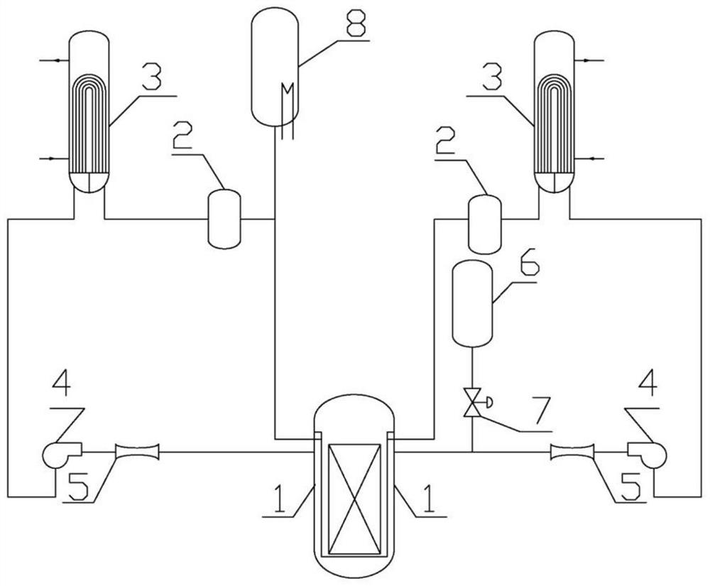
[0033] A test device for an automatic chemical shutdown system, comprising a reactor pressure vessel 1, a primary loop system connected with the inlet and outlet of the reactor pressure vessel 1 to form a circulation loop, a pressure gauge and a thermometer arranged on the inlet and outlet of the reactor pressure vessel 1, set Passive automatic chemical shutdown system to be tested on the primary loop system, and voltage regulator 8.

[0034] The specific settings of the structure of this embodiment are as follows:

[0035] The primary loop system includes a boric acid elimination device 2, a steam generator 3, a main coolant pump 4 and a flow meter 5 connected in sequence; the flow meter 5 is communicated with the inlet of the reactor pressure vessel 1, and the boric acid elimination device 2 is connected to the reactor The outlet of the pressure vessel 1 is communicated.

[0036] Two sets of four inlet and outlet ports are designed on the barrel of the reactor pressure vess...

Embodiment 2

[0051] This embodiment further optimizes the setting method of the rich boron detector 10 in the reactor pressure vessel 1 on the basis of the first embodiment, such as figure 2 The specific settings are as follows:

[0052] A boric acid detector 10 is arranged between the electric heating element rods 9; the heating power of the electric heating element rod 9 is controlled by a heating element control system, and the boric acid detector 10 is connected with the heating element control system. The passive boron injection box 6 injects boric acid into the primary loop system, and the boric acid detector 10 in the core measures the boric acid concentration entering each channel in the core accurately in real time, and the measurement results are fed back to the heating element control system. The heating power of each electric heating element rod 9 is adjusted according to the measurement and calculation results.

[0053] In this embodiment, a plurality of boric acid detectors...

Embodiment 3

[0064] The difference between this embodiment and Embodiment 1 or Embodiment 2 is that the flowmeter 5 in this embodiment is preferably a Venturi flowmeter, a V-cone flowmeter, an orifice flowmeter, a mass flowmeter or an ultrasonic flowmeter.


PUM


Abstract

The invention discloses a test device and a test method of an automatic chemical shutdown system. The invention includes a reactor pressure vessel, a primary circuit system connected with the inlet and outlet of the reactor pressure vessel to form a circulation loop; a pressure gauge and a thermometer arranged on the inlet and outlet of the reactor pressure vessel; the primary circuit system includes a boric acid elimination device connected in sequence , steam generator, main coolant pump and flow meter; the inlet and outlet of the reactor pressure vessel are more than two groups, the number of primary loop systems is the same as that of the reactor pressure vessel, and one of the primary loop systems is used to connect non- In the active automatic chemical shutdown system, a voltage stabilizer is connected to one of the primary loop systems; the core of the reactor pressure vessel adopts electric heating element rods to simulate nuclear fuel rods. The research results obtained by the invention can be used for the verification and optimization of the automatic chemical shutdown system of the nuclear reactor, so as to improve the inherent safety performance of the nuclear reactor.

Description

technical field [0001] The invention relates to the field of nuclear reactor safety, in particular to a testing device for an automatic chemical shutdown system and a testing method thereof. Background technique [0002] The expected transient ATWS that fails to scramble the reactor means that although the thermal parameters such as the temperature and pressure of the primary or secondary loop of the nuclear reactor exceed the protection thresholds, the control rod assembly does not fall due to the sticking rod and other reasons, and the reactor does not have an emergency shutdown. The expected transient of the heap. [0003] When an ATWS accident occurs in the reactor, the automatic chemical shutdown system adopts a passive method to inject concentrated boron water into the core to realize emergency shutdown and protect the safety of the reactor. Therefore, the design, test verification, optimization and engineering application of the automatic chemical shutdown system are...

Claims


Application Information

Patent Timeline
Patent Type & Authority Patents(China)
IPC IPC(8): G21C17/00G21C17/003G21C17/028
CPCG21C17/00G21C17/003G21C17/028Y02E30/30
Inventor 彭传新林欣茹张妍闫晓昝元锋卓文彬杨帆
Owner NUCLEAR POWER INSTITUTE OF CHINA
Why Eureka
Try Eureka