Motor rotating shaft with forced cooling device

A technology of forced cooling and motor shaft, which is applied in the direction of cooling/ventilation devices, electromechanical devices, and control of mechanical energy. It can solve the problems of limited installation space, increased use costs, and increased system complexity, so as to improve cooling efficiency and improve cooling efficiency. effect of effect

Inactive Publication Date: 2019-03-15
JIANGSU JINPENG VEHICLE CO LTD
View PDF0 Cites 1 Cited by
  • Summary
  • Abstract
  • Description
  • Claims
  • Application Information

AI Technical Summary

Problems solved by technology

This increases the complexity of the system
For electric vehicles, the installation space is limited, and additional power sources require additional maintenance and maintenance, and the later use costs will increase

Method used


Image

  • Motor rotating shaft with forced cooling device
  • Motor rotating shaft with forced cooling device
  • Motor rotating shaft with forced cooling device

Examples


Embodiment Construction

[0021] The invention will be described in detail below in conjunction with the accompanying drawings.

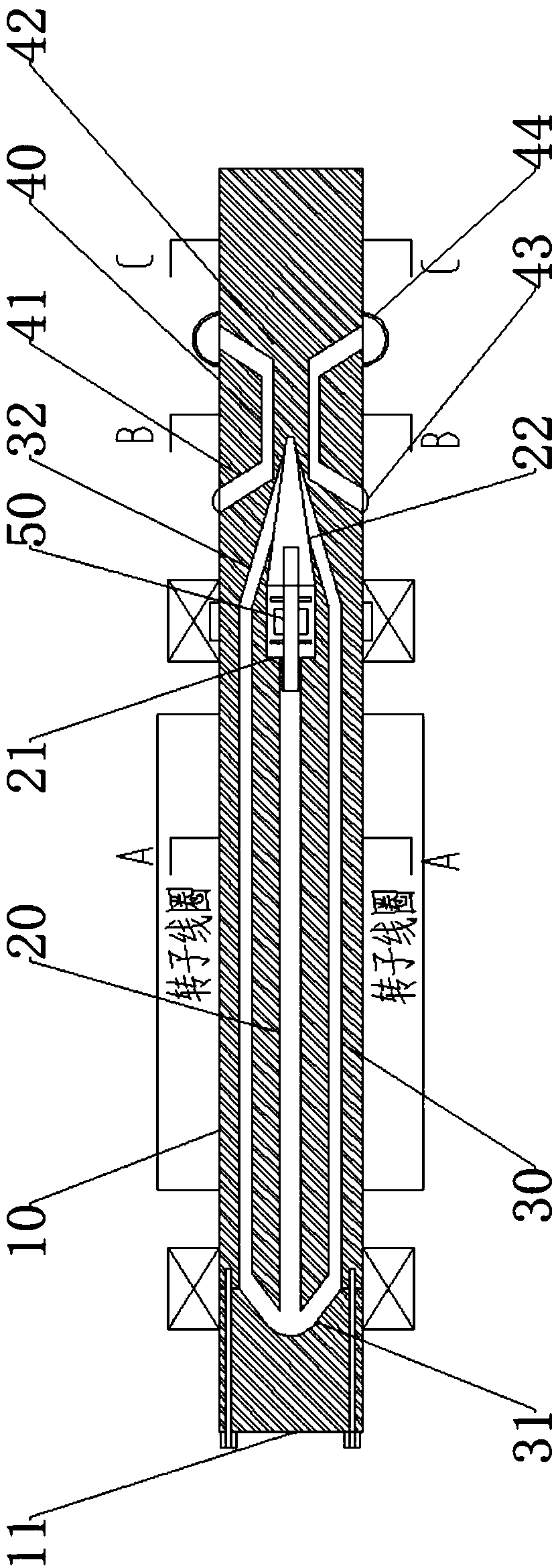
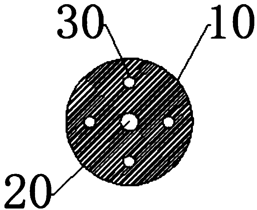
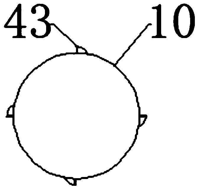
[0022] Such as Figures 1 to 5 As shown, a motor shaft with a forced cooling device includes a shaft body 10 . Inside the shaft body 10, there is a coaxial central cavity 20. The longitudinal section of the central cavity 20 is circular, its diameter is 1 / 8-1 / 4 of the diameter of the shaft body 10, and its axial ends are located between the fixed point of the bearing. One end of the central cavity 20 communicates with the coaxial cylindrical cavity 21, the diameter of the cylindrical cavity 21 is 1 / 4-1 / 3 of the diameter of the shaft body 10, and the length of the cylindrical cavity 21 is 1 / 10-1 / 10 of the central cavity 20 1 / 6, the end of the cylindrical cavity 21 away from the central cavity 20 is connected to the coaxial conical cavity 22, the conical bottom of the conical cavity 22 coincides with the end face of the cylindrical cavity, and the length of the conical cavity...


PUM


Abstract

The invention discloses a motor rotating shaft with a forced cooling device. The interior of the shaft body is coaxially provided with a central cavity, and the longitudinal section of the central cavity is circular. One end of the central cavity is communicated with an axial cylindrical cavity, and one end, far from the central cavity, of the cylindrical cavity is communicated with an axial conical cavity. The periphery of the central cavity is provided with a plurality of concentric cavities. The axes of the plurality of concentric cavities are parallel to the axis of the central cavity, andare uniformly distributed along the axis of the central cavity. The interior of the shaft body is provided with an arc cavity, and the arc cavity is coaxial with the central cavity, wherein the center is communicated with one end, far from the cylindrical cavity, of the central cavity, and the peripheral edge is communicated with one end, far from the cylindrical cavity, of the concentric cavity.The rotating shaft also comprises a pressurizing assembly which performs the pressurization of the vaporized liquid, and the central cavity, the cylindrical cavity, the conical cavity, the concentriccavities and an inclined tube form a cooling cavity. The interior of the cooling cavity is provided with cooling liquid, and the air pressure in the cooling cavity is 0.3-0.4 standard atmospheric pressure. The cylindrical cavity and the conical cavity extend out of an axial range wrapped by a rotor coil. The rotor shaft can form a spontaneous gas-liquid circulation system in the operation, and effectively improves the cooling efficiency of the motor.

Description

technical field [0001] The invention relates to a motor shaft, in particular to a liquid-cooled motor shaft with a forced cooling device that can be used by an electric vehicle. Background technique [0002] Existing motor liquid cooling is basically liquid-cooled for the housing or internal cavity of the motor. The rotor of the motor is in constant motion, so it is not easy to be directly liquid-cooled, but the temperature of the rotor is no different from that of other parts. Therefore, the temperature of the rotor is usually the highest inside the pure liquid-cooled motor. It is difficult to liquid-cool the rotating shaft. If the cooling liquid is simply used to fill the cavity of the rotating shaft, due to the very limited circulation space of the cooling liquid, the required cooling effect will not be achieved after the motor has been working for a long time. [0003] In addition, to perform forced cooling on the motor shaft, it is generally necessary to add an additio...

Claims


Application Information

Patent Timeline
Patent Type & Authority Applications(China)
IPC IPC(8): H02K7/00H02K9/20
CPCH02K7/003H02K9/20H02K2213/03
Inventor 鹿世敏朱东风朱红军鹿尧
Owner JIANGSU JINPENG VEHICLE CO LTD
Why Eureka
Try Eureka