Detection device and system for remaining time of drip

A technology of residual time and detection device, which is applied in the direction of control/adjustment system, hypodermic injection equipment, flow control, etc., can solve the problems of manpower consumption, low versatility, expensive use of drip equipment, etc., and achieve reasonable arrangement of time Effect

Inactive Publication Date: 2019-03-19
壹妙芯(厦门)科技有限公司 +1
View PDF42 Cites 1 Cited by
  • Summary
  • Abstract
  • Description
  • Claims
  • Application Information

AI Technical Summary

Problems solved by technology

However, for the direct use of drip flow rate control equipment provided by the hospital, because professional drip equipment is expensive to use, and the main function of the equipment is to control the flow rate of drip medicine, it is aimed at patients with special treatment, and its versatility is not high.
For manual observation of drip volume, it consumes manpower and cannot be accurately estimated, regular observation is required

Method used


Image

  • Detection device and system for remaining time of drip
  • Detection device and system for remaining time of drip
  • Detection device and system for remaining time of drip

Examples


no. 1 example

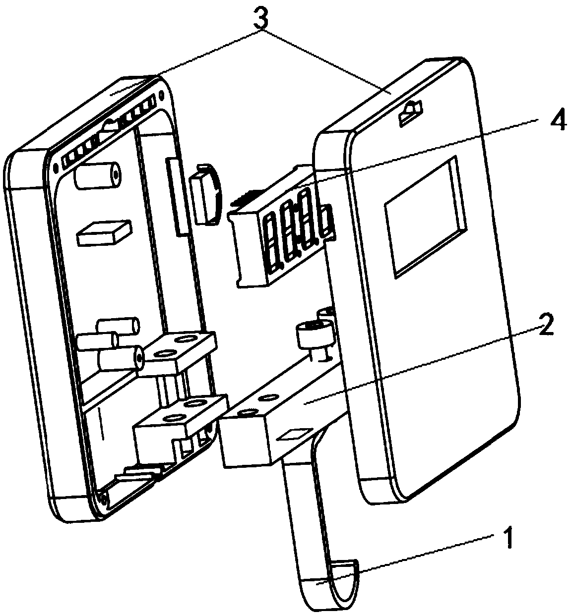
[0036] see Figure 1 to Figure 2 , the first embodiment of the present invention provides a device for detecting the remaining time of infusion, which specifically includes the following:

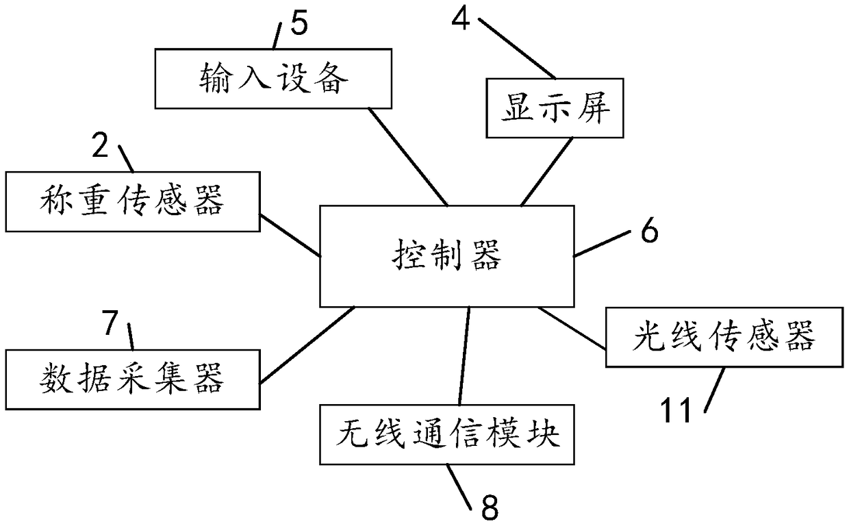
[0037] The first hook 1, the load cell 2, the controller 6 and the wireless communication module 8; one end of the first hook 1 forms a hook for hanging the drip bottle, and the load cell 2 It is arranged at the other end of the first hook 1 ; the controller 6 is electrically connected with the load cell 2 and the wireless communication module 8 .

[0038] In this embodiment, the first hook 1 may be a hook, one end of which is hooked to hook the drip bottle. It should be noted that, in other embodiments of the present invention, the first hook 1 may also be a clip or a hoop, as long as it can be used to hook the drip bottle. within the scope of the invention.

[0039] In this embodiment, the load cell 2 is a device that converts the mass signal into a measurable electrical signal output....

no. 2 example

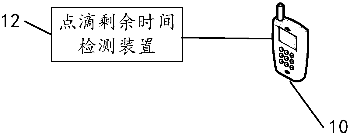
[0065] see image 3 with Figure 4 The second embodiment of the present invention provides a system for detecting the remaining time of infusion, which specifically includes: a server 9, at least one user terminal 10, and the device for detecting the remaining time of infusion as described in any of the above-mentioned embodiments. In this embodiment, the user terminal may be a mobile terminal 20 or a mobile communication terminal, which refers to a computer device that can be used on the move, broadly speaking, it includes a personal computer (Personal Computer, PC), a personal digital assistant (Personal Digital Assistant) Assistant, PDA), mobile phone (Mobile Phone, MP), POS machine and even vehicle-mounted computer and other electronic devices capable of wireless communication. The server 9 adopts a distributed architecture, and designs and divides subsystems / modules according to the service objects of each business system unit; among them, it includes a decision-making a...


PUM


Abstract

The invention discloses a detection device and system for remaining time of a drip. The device comprises a first hanging part, a weighing sensor, a control and a wireless communication module; a hanging portion for hanging a drip bottle is formed in one end of the first hanging part, and the weighing sensor is arranged at the other end of the first hanging part; the controller, the weighing sensorand the wireless communication module are electrically connected. The controller comprises a processor and a storage, and an executable code is stored in the storage and configured to be executed bythe processor according to the following implementation method. The implementation method comprises the steps that an initial capacity value and a current weight valve of a current-hung drip bottle and a weight difference of the drip bottle in a preset time period are acquired, and according to the weight difference of the drip bottle in the preset time period, the current flow speed of the drip bottle is calculated; according to the initial capacity value, the current flow speed and the current weight valve, the remaining time of the drip is calculated and sent to a server through the wireless communication module, so that the server sends the remaining time to a related user terminal.

Description

technical field [0001] The invention relates to the technical field of medical equipment, in particular to a device and system for detecting remaining time of infusion. Background technique [0002] With the development of China's medical level and the deepening of the aging population, the number of hospital visits continues to increase. Among them, drip therapy is widely adopted in hospitals, and is used in the treatment of various diseases. However, in the actual drip treatment process, especially for patients who need to change the drip medicine, the patient or accompanying family members cannot make an accurate estimate of the time required for the drip, and cannot notify the hospital nurse in time to replace the drip. During the treatment process, a lot of time is spent waiting for observation costs, and for the accompanying family members of critically ill patients, there is a waiting state for nursing care 24 hours a day, and it is impossible to arrange time reasonab...

Claims


Application Information

Patent Timeline
Patent Type & Authority Applications(China)
IPC IPC(8): A61M5/168
CPCA61M5/16804A61M5/16845A61M2205/505A61M2205/52
Inventor 林志铿谢艺浜谢鸿清林伟年曾剑祥
Owner 壹妙芯(厦门)科技有限公司
Why Eureka
Try Eureka