Rice polishing device

A polishing device and rice technology, applied in grain finishing, grain processing, application, etc., can solve the problems of easy clogging of internal pipes, inability to wet rice, broken rice, etc., improve polishing uniformity, and facilitate installation and disassembly. , to avoid the effect of blocking the pipeline

Inactive Publication Date: 2019-03-19
颍上县皖润米业有限公司
View PDF4 Cites 3 Cited by
  • Summary
  • Abstract
  • Description
  • Claims
  • Application Information

AI Technical Summary

Problems solved by technology

[0003] The existing rice polishing device has certain disadvantages in use. First, it cannot moisten the rice, which is not conducive to completely grinding off the rice bran, and cannot improve the smoothness and polishing uniformity of the rice. The phenomenon of broken rice is relatively high. The polishing chamber can be uniformly exhausted, the bran powder produced by polishing cannot be completely blown out of the polishing tube, and the polished rice cannot be dried. Finally, the traditional polishing device has a complicated structure and cannot clean the inner feeding chamber and the polishing chamber. It is inconvenient to clean the material receiving chamber for inspection and maintenance, and it is easy to block the internal pipeline, which has a certain impact on people's use process. Therefore, we propose a rice polishing device

Method used


Image

  • Rice polishing device
  • Rice polishing device
  • Rice polishing device

Examples


Embodiment 1

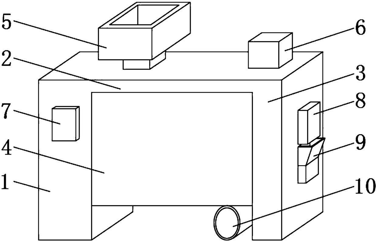
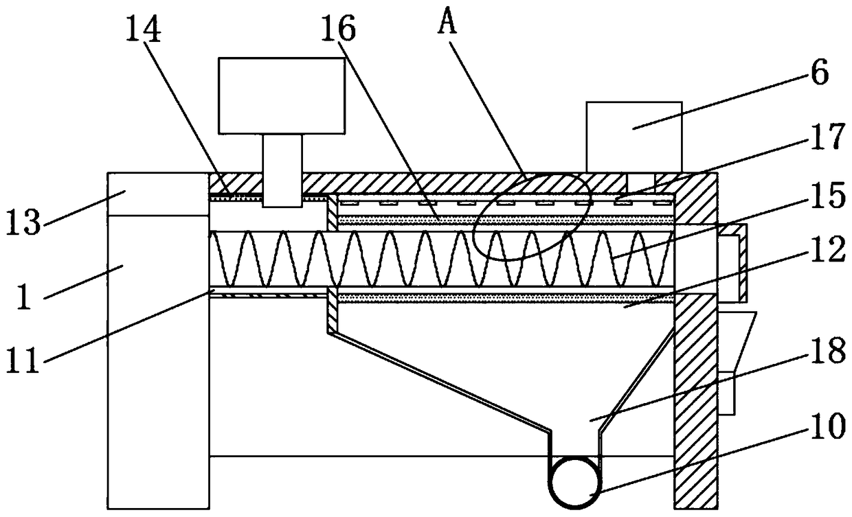
[0025] Such as Figure 1-4 As shown, a rice polishing device comprises a main body box 1 and a top plate 2, the top plate 2 is fixedly installed on the upper end of the main body box 1, the bottom end of the top plate 2 is fixedly installed with a bottom box 3, and the bottom end of the top plate 2 is fixedly installed with a feed The chamber 11 and the polishing chamber 12, and the feeding chamber 11 and the polishing chamber 12 are all located between the main body box 1 and the bottom box 3, the feeding chamber 11 is located on one side of the polishing chamber 12, and the inner top of the feeding chamber 11 is fixedly installed with Water spray plate 14, the upper end of water spray plate 14 is provided with several groups of drainage holes.

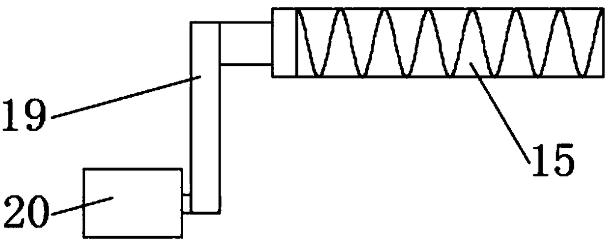
[0026] The inside of the polishing chamber 12 is fixedly equipped with a polishing tube 16, and the inside of the polishing tube 16 is penetrated with a roller 15. Inside the material chamber 11, the outer surface of one side of the...

Embodiment 2

[0032] Such as Figure 1-4 As shown, it includes a main body box 1 and a top plate 2, the top plate 2 is fixedly installed on the upper end of the main body box 1, the bottom end of the top plate 2 is fixedly installed with a bottom box 3, and the bottom end of the top plate 2 is fixedly installed with a feeding chamber 11 and a polishing chamber 12 , and both the feeding chamber 11 and the polishing chamber 12 are located between the main body case 1 and the bottom case 3 , and the feeding chamber 11 is located on one side of the polishing chamber 12 .

[0033] The inside of the polishing chamber 12 is fixedly equipped with a polishing tube 16, and the inside of the polishing tube 16 is penetrated with a roller 15. In the inside of material chamber 11 , the inner top of polishing chamber 12 is fixedly equipped with air duct 17 , and air duct 17 is located at the upper end of polishing pipe 16 , and the bottom end of air duct 17 is connected with several groups of exhaust pipe...

Embodiment 3

[0039] Such as Figure 1-4 As shown, it includes a main body box 1 and a top plate 2, the top plate 2 is fixedly installed on the upper end of the main body box 1, the bottom end of the top plate 2 is fixedly installed with a bottom box 3, and the bottom end of the top plate 2 is fixedly installed with a feeding chamber 11 and a polishing chamber 12 , and the feeding chamber 11 and the polishing chamber 12 are all located between the main body box 1 and the bottom box 3, the feeding chamber 11 is located on one side of the polishing chamber 12, and the inner top of the feeding chamber 11 is fixedly equipped with a water spray plate 14, spraying The upper end of the water plate 14 is provided with several groups of drainage holes.

[0040] The front end of the feeding chamber 11 and the polishing chamber 12 is provided with a front cover 4, and the front cover 4 is fixedly connected with the main body box 1 and the bottom box 3 respectively. The lower end of the polishing chamb...


PUM


Abstract

The invention discloses a rice polishing device. The rice polishing device comprises a body box and a top plate fixedly arranged at the upper end of the body box. A bottom box is fixedly arranged at one end of the bottom of the top plate. A feeding chamber and a polishing chamber are fixedly arranged at the bottom end of the top plate. According to the rice polishing device, water can be evenly sprayed to rice entering the feeding chamber, rice wetting is convenient, rice bran can be better thoroughly removed through grinding, the smooth finish and polishing uniformity of rice are improved, crushed rice is reduced, uniform exhausting can be conducted on the polishing chamber, bran powder generated due to polishing can be blown out of a polishing pipe, falls into a material receiving chamber and is discharged through a bran powder discharging pipe. Meanwhile, the rice obtained after polishing is dried, a front cover arranged at the front end can be convenient to mount and dismount, detection and maintenance can be conducted on the inner feeding chamber and the polishing chamber, the material receiving chamber can be conveniently cleaned, inner cleanliness is kept, pipeline blockageis avoided, and better usage prospects are brought.

Description

technical field [0001] The invention relates to the field of rice polishing devices, in particular to a rice polishing device. Background technique [0002] Rice becomes brown rice after husking. Brown rice becomes rice after removing most of the cortex and part of the germ. There is a small amount of bran powder on the surface of the rice grains of large white rice, which affects the appearance, quality, storage and taste of the rice. Therefore, This part of the bran powder needs to be removed through the polishing process. Polishing is one of the key processes in cleaning rice processing. Because polishing can remove the bran powder on the surface of rice grains, proper polishing can make the starch on the surface of rice grains colloidal, showing a certain brightness and appearance. Well, the value of the product increases, and rice polishing devices are often used for polishing; [0003] The existing rice polishing device has certain disadvantages in use. First, it cann...

Claims


Application Information

Patent Timeline
Patent Type & Authority Applications(China)
IPC IPC(8): B02B3/04
CPCB02B3/04
Inventor 杨立健
Owner 颍上县皖润米业有限公司
Why Eureka
Try Eureka