Apparatus cleaning device for pneumology department

A cleaning device and equipment technology, which is applied in the field of equipment cleaning, can solve the problems of troublesome and laborious cleaning, incomplete cleaning of endotracheal tubes, and difficult cleaning of endotracheal tubes, etc. It achieves the advantages of ingenious design, excellent cleaning effect, and ease of work difficulty Effect

Active Publication Date: 2019-03-19
汪铮
View PDF6 Cites 21 Cited by
  • Summary
  • Abstract
  • Description
  • Claims
  • Application Information

AI Technical Summary

Problems solved by technology

[0004] In view of the above problems, the present invention provides a device cleaning device for respiratory department, which solves the problem that the trachea

Method used


Image

  • Apparatus cleaning device for pneumology department
  • Apparatus cleaning device for pneumology department
  • Apparatus cleaning device for pneumology department

Examples


Embodiment 1

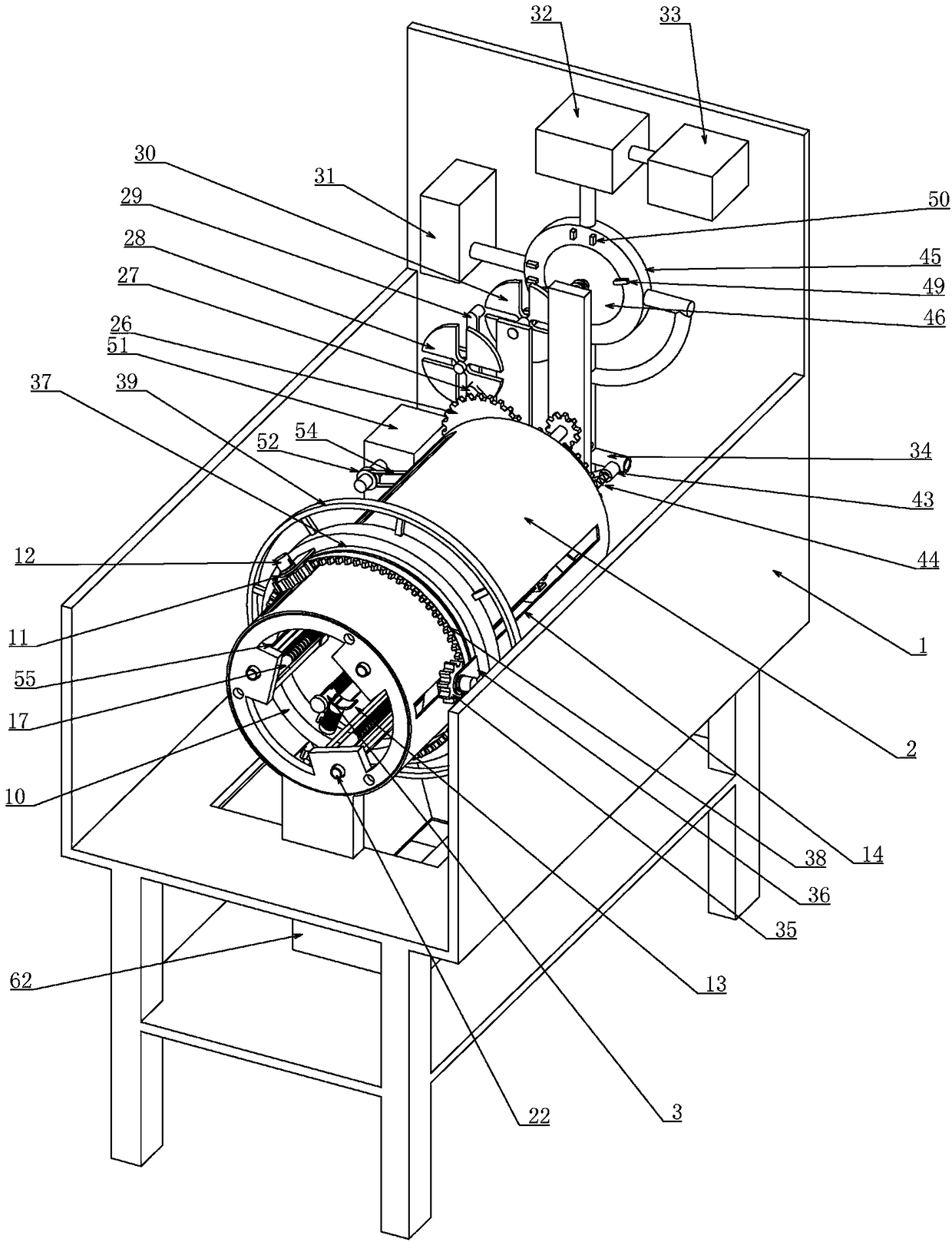
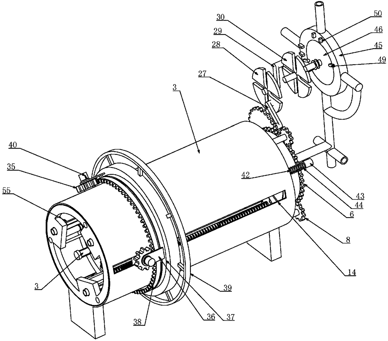
[0036] Embodiment one, combined with the attached Figure 1-16 , a device cleaning device for respiratory department, comprising a bracket 1, characterized in that, the upper end of the bracket 1 is longitudinally installed with a fixed cylinder 2 with a closed rear end surface, the front end of the fixed cylinder 2 is open, and the rear end surface of the fixed cylinder 2 is The coaxial rotation passes through an inner hollow main shaft 3, the main shaft 3 is connected with the rear end surface of the fixed cylinder 2 in rotation, the main shaft 3 passes through the rear end surface of the fixed cylinder 2 and extends back and forth, and the diameter of the main shaft 3 is smaller than the diameter of the tracheal intubation tube used in the respiratory department , the choice of the material of the main shaft 3 is to choose a material with higher strength as far as possible, the main shaft 3 is coaxially connected to a driving gear 4 placed behind the fixed cylinder 2, and th...

Embodiment 2

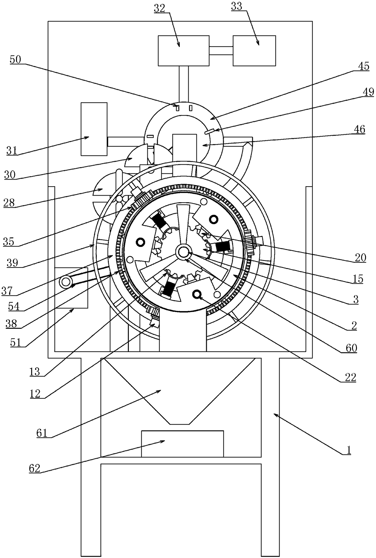
[0040] Embodiment two, on the basis of embodiment one, in conjunction with the attached Figure 1-16, the drive device includes a spur gear 35 coaxially connected with the sleeve 11 and placed outside the fixed cylinder 2, the sleeve 11 is connected with a fixed plate 36, and the fixed plate 36 extends backward, and the three sets of fixed plates 36 The rear end is slidably matched with a collar 37 coaxially arranged with the fixed cylinder 2, so that the collar 37 can only rotate along the axial direction of the fixed cylinder 2 relative to the fixed plate 36. T" shaped slider 18, the collar 37 is provided with a cross-section that matches the inverted "T" shaped slider 18 on the fixed plate 36 and is an inverted "T" shaped chute, so that the collar 37 only wants to fix the When the barrel 2 rotates, the front end of the collar 37 is connected to a face gear 38 meshing with three sets of spur gears 35, and the face gear 38 drives the spur gear 35 to rotate. At this time, the ...

Embodiment 3

[0041] Embodiment three, on the basis of embodiment one, in conjunction with the attached Figure 1-16 The pretensioning device includes a vertical rod 42 that is rotatably connected to the side wall of the fixed cylinder 2. The position of the vertical rod 42 is set at the position where the outer ring gear 6 and the driven gear 5 are disengaged. The rear of the vertical rod 42 is The end is rotatably connected with a drive plate 43 that cooperates with the column pin 7. A torsion spring 44 sleeved outside the vertical rod 42 is connected between the drive plate 43 and the fixed cylinder 2. The column pin 7 rotates to the stroke with the outer ring gear 6. At the end point, the column pin 7 will be driven to rotate. At this time, due to the existence of the torsion spring 44, the driving plate 43 always has the force to return to the initial position. After the outer ring gear 6 rotates outward, the torsion spring 44 will Drive the drive plate 43 back to the initial position,...


PUM


Abstract

The invention relates to an apparatus cleaning device for the pneumology department. According to the apparatus cleaning device for the pneumology department, a plurality of sets of planetary wheel structures are ingeniously applied, and the structural specificity of an external gear ring is utilized to convert forward and reverse rotating of a motor into different working processes; through the incompleteness of inner teeth of the external gear ring, when the external gear ring is about to be disengaged from a driven gear at a meshing terminal, a set of pre-tensioning device is added, and then the external gear ring is limited at the position of the meshing terminal of the external gear ring and the driven gear wheel, and reliable meshing can be realized when the external gear ring rotatereversely; and meanwhile, transition grooves and rectangular grooves in different positions are made alternately communicate through relative rotation of a circle plate and a fixing plate, and different processes are achieved. According to the apparatus cleaning device for the pneumology department, the transmission characteristics of a screw rod and a reciprocating screw rod are fully utilized to realize reciprocating characteristics of tracheal intubation and cleaning and drying work, the design is ingenious, the operation is simple, cleaning personnel are liberated greatly, working difficulty of the cleaning personnel is lowered, and the cleaning effect is excellent.

Description

technical field [0001] The invention belongs to the technical field of instrument cleaning, in particular to an instrument cleaning device for respiratory department. Background technique [0002] The Department of Respiratory Medicine includes Respiratory Internal Medicine and Respiratory Surgery. Auxiliary devices are used in the treatment of respiratory diseases. Therefore, many types of medical cleaning devices have emerged as the times require, which has greatly liberated the staff and reduced their workload. However, some The cleaning machine cannot completely clean the used medical equipment, because improper cleaning will damage the medical equipment and increase the hospital's expenditure, and incomplete cleaning can easily cause cross-infection of patients, especially now that medical equipment needs to be cleaned after cleaning Drying, incomplete drying will also affect the use of medical devices; [0003] At present, in the medical discipline of respiratory depa...

Claims


Application Information

Patent Timeline
IPC IPC(8): B08B9/023B08B9/032F26B21/00A61B90/70
CPCA61B90/70A61B2090/701B08B9/023B08B9/0321B08B2209/02F26B21/00
Inventor 汪铮张晓菊郭琼雅李楠安云霞杨会珍朱敏李晓王月霞席芳张静静
Owner 汪铮
Why Eureka
Try Eureka