Sewing machine pneumatic lifting electronic mop mechanism and control method thereof

A pneumatic lifting and sewing machine technology, which is applied in the direction of sewing machine control devices, sewing machine components, sewing equipment, etc., can solve the problems such as insufficient response of mop wheel mop cloth, failure to meet low-end customers, driven shaft and synchronous belt breakage, etc. Achieve the effect of improving mop congestion, simple structure, and reducing the phenomenon of needle loss

Pending Publication Date: 2019-03-19
XIAN TYPICAL IND
View PDF0 Cites 1 Cited by
  • Summary
  • Abstract
  • Description
  • Claims
  • Application Information

AI Technical Summary

Problems solved by technology

Therefore, the structure of the mechanism is complicated, the parts are numerous, and the cost is high, which cannot meet the needs of low-end customers.
Moreover, when the current traditional electronic mop mechanism is running at a relatively high speed, due to the single supporting force of the driven shaft and the narrow width of the timing belt, it is easy to cause the breakage of the driven shaft and the timing belt; , the movement is not smooth enough during operation, the response of the mop wheel mop is not timely enough, and the phenomenon of needle drop during sewing is reduced

Method used


Image

  • Sewing machine pneumatic lifting electronic mop mechanism and control method thereof
  • Sewing machine pneumatic lifting electronic mop mechanism and control method thereof
  • Sewing machine pneumatic lifting electronic mop mechanism and control method thereof

Examples


Embodiment Construction

[0035] The present invention is described in detail below in conjunction with accompanying drawing:

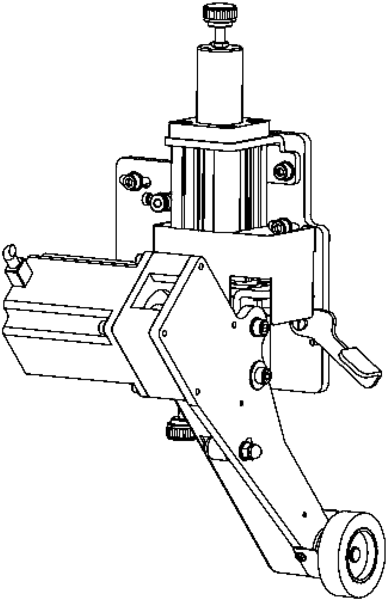
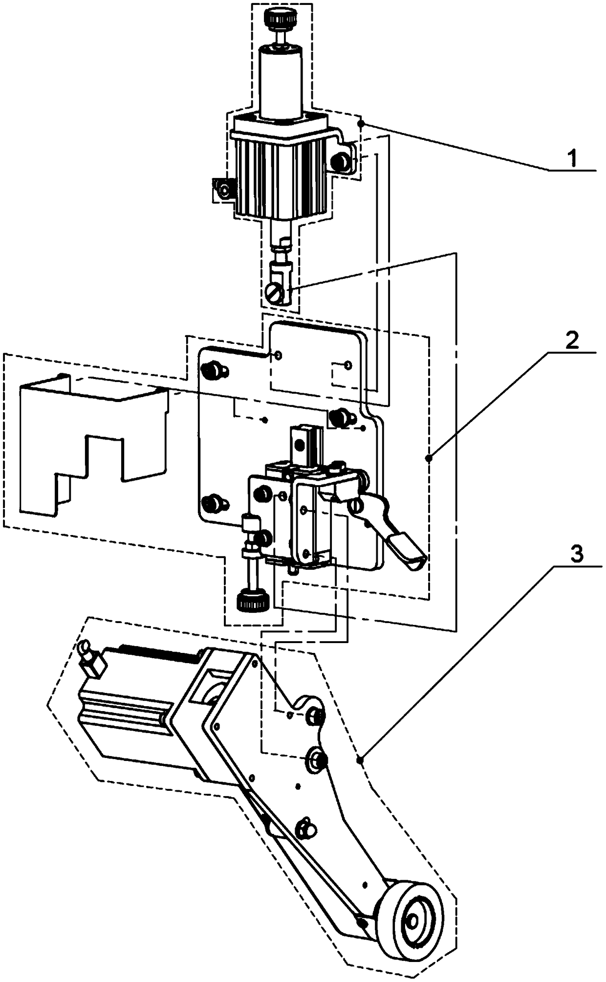
[0036] A sewing machine pneumatic lifting electronic mop mechanism (see Figure 1-Figure 2 ), including an integrated pneumatic lifting and pressing component 1, a vertical guide adjustment component 2 and an electronic mop executing component 3;

[0037] The one-piece pneumatic lifting and pressing assembly 1 (see image 3 ) including pressure regulating screw 1-1, pressure regulating nut 1-2, spring guide sleeve 1-3, spring pressing block 1-4, spring 1-5, screw one 1-6, fixing block 1-7, screw two 1 -8, large washer 1-9, cylinder bracket 1-10, screw three 1-11, double action cylinder 1-12, nut 1-13, cylinder joint 1-14 and shaft screw 1-15;

[0038]The fixed block 1-7, the cylinder bracket 1-10 and the double-action cylinder 1-12 are arranged in sequence and connected by the screw 1-6, and the pressure regulating nut 1-2 is threaded with the pressure regulating screw 1-1. ...


PUM


Abstract

The invention relates to the technical field of sewing, in particular to a sewing machine pneumatic lifting electronic mop mechanism and a control method thereof. The mechanism is simple in structure,components are simplified, the biasing force exerted on the mechanism is reduced, the service life of a double-acting cylinder and a linear guide assembly is favorably prolonged, needle loss during sewing can be prevented, the mop wheel lifting opportunity can be controlled, and the mop jam between the mop wheel and a presser foot is better relieved. The mechanism comprises an integrated pneumatic lifting and pressing assembly, the integrated pneumatic lifting and pressing assembly and a vertical guiding adjustment assembly are fixed to a main body fixing plate by screw connection, an electronic mop execution assembly is fixedly connected to a connecting support of the vertical guiding adjustment assembly, the transmitting end of a photoelectric detector is arranged between a mop wheel assembly in an electronic mop execution assembly and the sewing machine presser foot, and the receiving end of the photoelectric detector is disposed on the lower portion of the opposite sewing machinehead.

Description

technical field [0001] The invention relates to the field of sewing technology, in particular to a sewing machine pneumatic lifting electronic mop mechanism and a control method thereof. Background technique [0002] The lifting mechanism and the mop pressure applying mechanism of the current electronic mopping mechanism are different parts, and the lifting mechanism is lifted by spring rebound, and the cylinder only provides the function of stretching out to make the mopping wheel reach the mopping position; the motor of the current electronic mopping mechanism The pulley and the driven wheel are respectively installed on two plates, and the tension of the synchronous belt is also tensed by increasing the separation distance between the two plates. Therefore, the structure of the mechanism is complex, the parts are numerous, and the cost is high, which cannot meet the needs of low-end customers. And at present, when the traditional electronic mop mechanism is running at a ...

Claims


Application Information

Patent Timeline
Patent Type & Authority Applications(China)
IPC IPC(8): D05B33/00D05B69/08D05B69/10D05B69/02
CPCD05B33/00D05B69/02D05B69/08D05B69/10
Inventor 刘永陈晓宇高小松蔡辉
Owner XIAN TYPICAL IND
Why Eureka
Try Eureka