Supercharge Your Innovation With Domain-Expert AI Agents!

Hydraulic filling retaining wall device and using method

A hydraulic device and hydraulic technology, applied in the direction of filling, safety device, earthwork drilling and mining, etc., can solve the problems of affecting production progress, wall cracking and sand running, long maintenance time, etc., and achieve high reuse rate and low labor intensity , good water filtration effect

Inactive Publication Date: 2019-03-19
GUIZHOU UNIV
View PDF6 Cites 1 Cited by
  • Summary
  • Abstract
  • Description
  • Claims
  • Application Information

AI Technical Summary

Problems solved by technology

The traditional retaining wall masonry has a large amount of engineering, long maintenance time, and poor bending resistance, which is prone to local displacement, deformation, cracking and even collapse, which leads to a large amount of slurry leakage
In order to avoid wall cracking, sand running, and slurry leakage accidents, the retaining wall is generally thickened, which not only affects the water filtration effect, but also wastes manpower and material resources, affects the production progress, and increases the filling cost

Method used


Image

  • Hydraulic filling retaining wall device and using method
  • Hydraulic filling retaining wall device and using method
  • Hydraulic filling retaining wall device and using method

Examples


Embodiment Construction

[0021] The following will clearly and completely describe the technical solutions in the embodiments of the present invention with reference to the accompanying drawings in the embodiments of the present invention. Obviously, the described embodiments are only some, not all, embodiments of the present invention. Based on the embodiments of the present invention, all other embodiments obtained by persons of ordinary skill in the art without making creative efforts belong to the protection scope of the present invention.

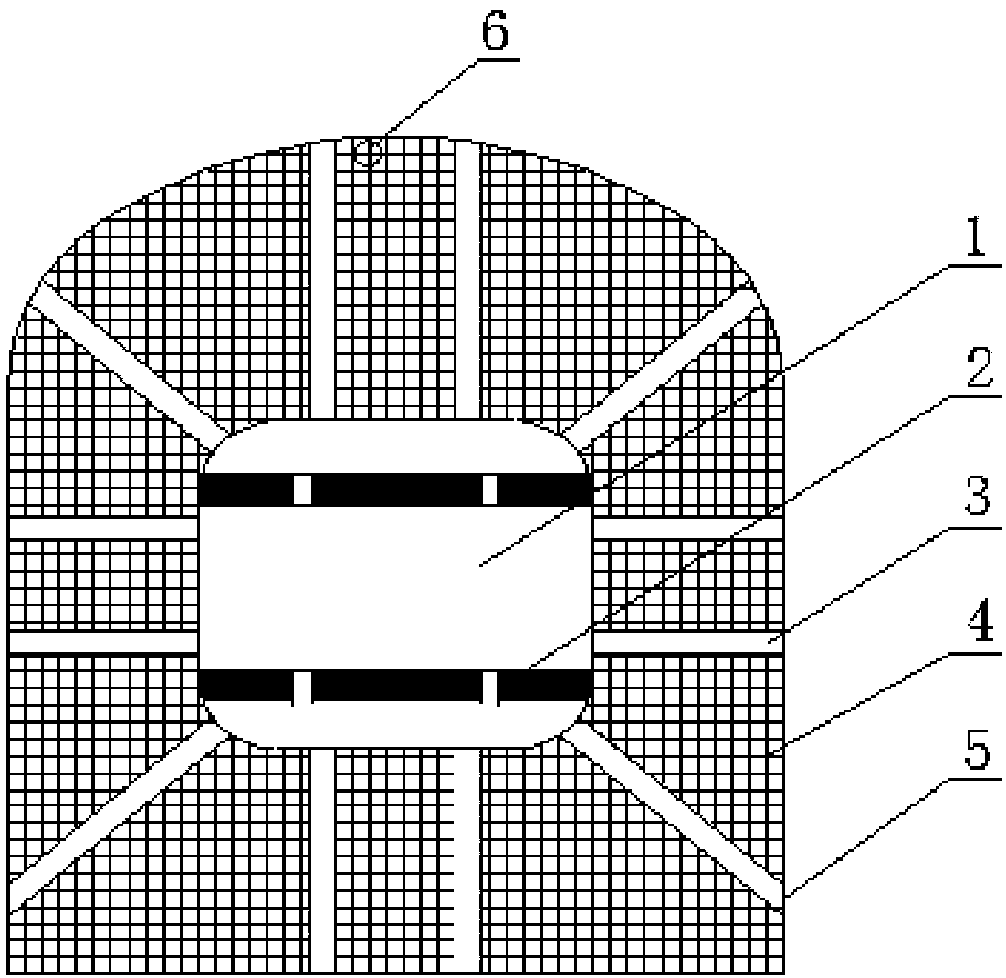
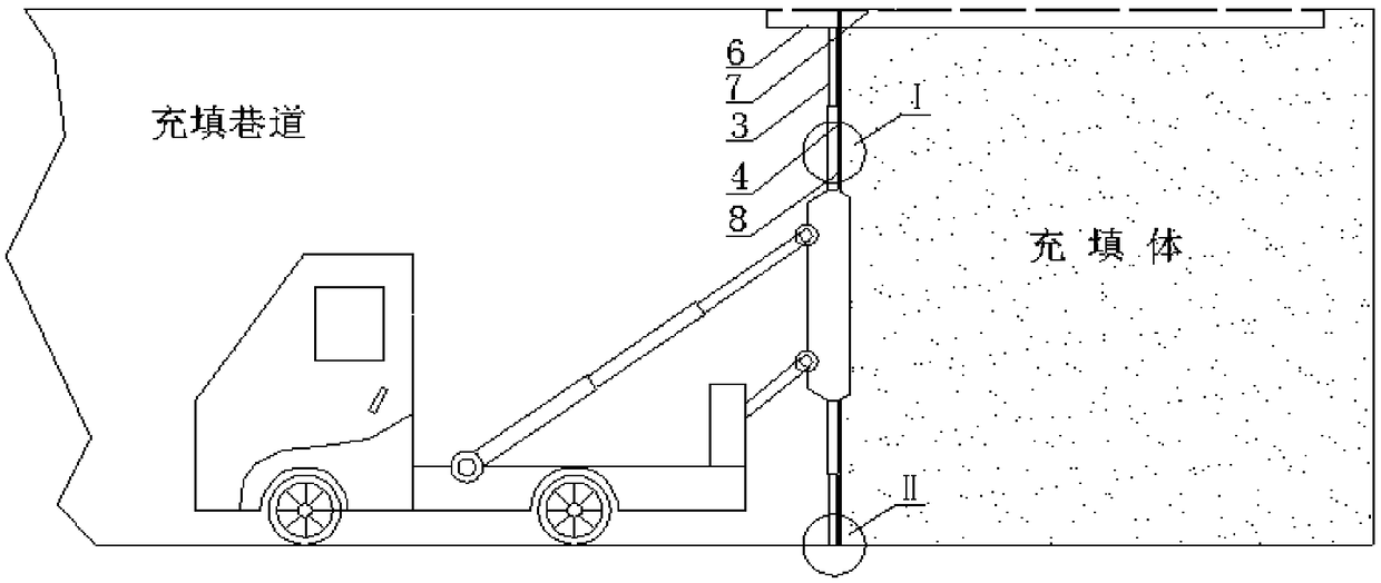
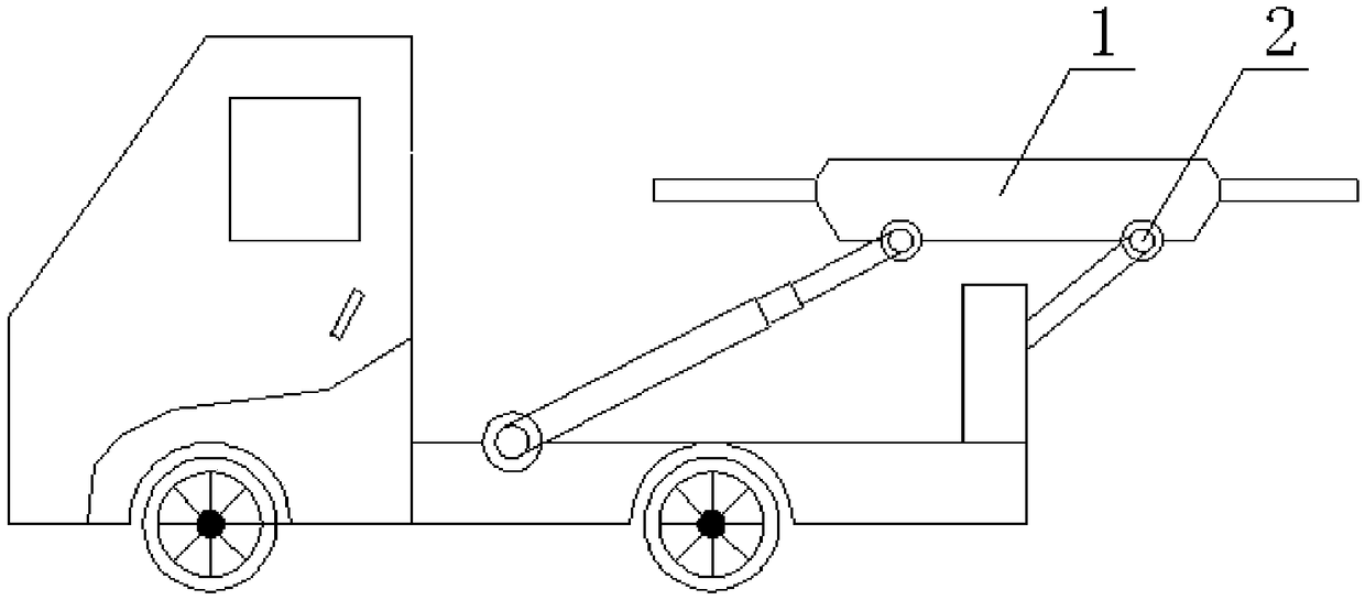
[0022] see Figure 1-4 , the present invention provides a technical solution: a hydraulic filling retaining wall device, including a hydraulic filling retaining wall vehicle located in the filling roadway, characterized in that: a hydraulic filling retaining wall is arranged on the rear side of the hydraulic filling retaining wall vehicle, and the hydraulic filling retaining wall At least 2 rows of hydraulic support legs 9 are set between the retaining wall ve...


PUM


Abstract

The invention discloses a hydraulic filling retaining wall device and a using method. The device comprises a hydraulic filling retaining wall vehicle, a hydraulic filling retaining wall is arranged onthe rear side of the hydraulic filling retaining wall vehicle, at least two rows of hydraulic supporting legs are arranged between the hydraulic filling retaining wall vehicle and the hydraulic filling retaining wall, and the two ends of each hydraulic supporting leg are provided with device guiding wheels respectively, so that the position of the hydraulic filling retaining wall is controlled bycontrolling the length or the steering angle of the hydraulic supporting legs; the hydraulic filling retaining wall includes a hydraulic device main body, hydraulic legs of double-cross-shape structures are uniformly distributed around the hydraulic device main body, the ends of the hydraulic legs are provided with hydraulic leg foot teeth, and a steel mesh and a geotextile filter cloth are laidon the back faces of the hydraulic legs in sequence; the upper end of the hydraulic filling retaining wall is provided with a filling pipe closely fitting the upper edge of a filling roadway, and a filling pipe support located on the upper edge of the filling roadway fixes the filling pip. The retaining wall overcomes the defects that traditional retaining walls are large in masonry workload, poorin bending resistance, high in cost, poor in safety and the like; the device has the advantages of being simple in structure, fast to install, good in drainability, low in labor intensity, high in repeated utilization rate, low in cost, safe, reliable and the like and lays a foundation for the development of a filling retaining wall technology in the future.

Description

technical field [0001] The invention relates to the technical field of hydraulic filling in underground mine filling mining method. Background technique [0002] After the backfilling mining method is adopted, the remaining mined-out area needs to be filled in time to manage the ground pressure, control the surrounding rock caving and surface movement, and ensure that the ore is mined on the formed filling body or under its protection. Sealing treatment must be carried out before filling the goaf to prevent the filling slurry from leaking, causing slurry loss and endangering normal roadway production. An important guarantee to realize its function within. The stability of the filling retaining wall plays an important role in the safety of underground mined-out areas, the safety of personnel and equipment, and the effective adjustment of mining-filling cycle. [0003] At present, the main filling retaining wall structures used in mines at home and abroad include concrete re...

Claims


Application Information

Patent Timeline
Patent Type & Authority Applications(China)
IPC IPC(8): E21F15/04
CPCE21F15/04
Inventor 郑禄璟褚洪涛
Owner GUIZHOU UNIV
Features
  • R&D
  • Intellectual Property
  • Life Sciences
  • Materials
  • Tech Scout
  • Unparalleled Data Quality
  • Higher Quality Content
  • 60% Fewer Hallucinations
Learn More