A Trough Solar Collector System with Stabilizer Intervals

A technology of solar collectors and trough solar energy, applied in the field of solar energy, can solve problems such as ineffective operation of collectors, different pressures of collector tubes, uneven fluid distribution, etc., to avoid uneven division, uniform distribution, and uniform pressure Effect

Active Publication Date: 2020-02-18
山东九泽换热系统有限公司
View PDF5 Cites 2 Cited by
  • Summary
  • Abstract
  • Description
  • Claims
  • Application Information

AI Technical Summary

Problems solved by technology

[0003] In solar collectors, the heat collecting tube structure is a very common form. This structure generally includes multiple parallel and side-by-side heat collecting tubes, but in operation, the fluid distribution in different heat collecting tubes often occurs unevenly. At the same time, there is also the fact that the temperature of the fluid in different heat collecting tubes is different due to uneven heating, which leads to different pressures in different heat collecting tubes
Long-term operation in this case will cause damage to the heat collecting tube with high pressure, which will cause the overall heat collector to be unable to operate effectively
[0004] In addition, during the heat exchange, the heat collecting tube absorbs solar energy to form a steam-water mixture. The existence of the vapor-liquid mixture causes the gas to mix together, and the heat exchange capacity between the liquid and the liquid decreases, which greatly affects the heat exchange efficiency.

Method used


Image

  • A Trough Solar Collector System with Stabilizer Intervals
  • A Trough Solar Collector System with Stabilizer Intervals
  • A Trough Solar Collector System with Stabilizer Intervals

Examples


Embodiment Construction

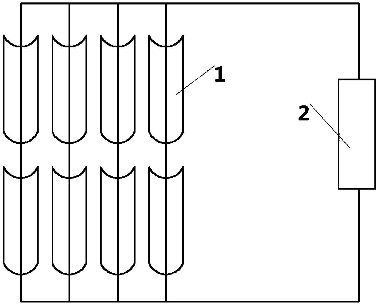
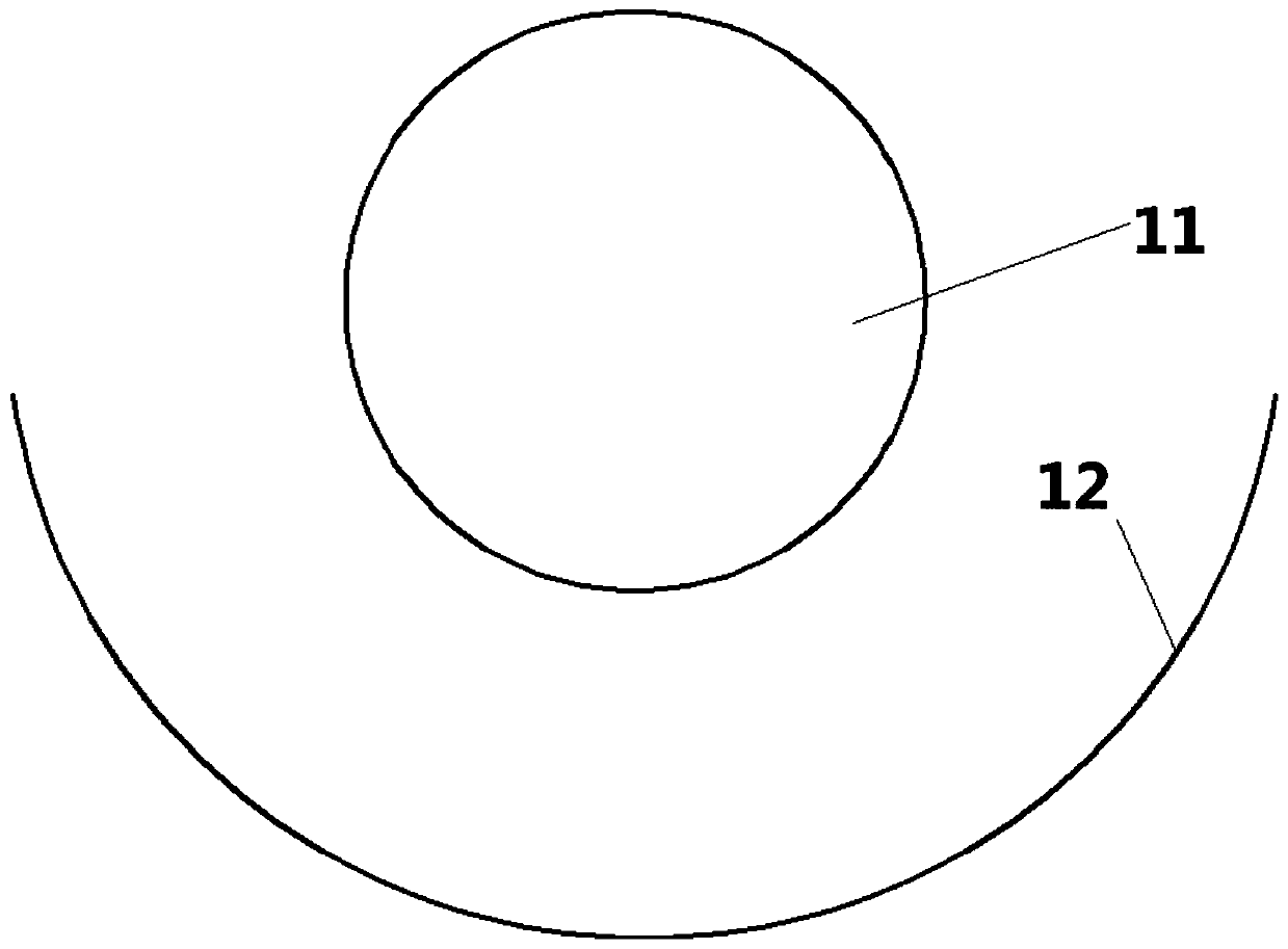
[0051] A trough solar heat collection system, such as Figure 1-2 As shown, the system includes a heat collector 1 and a heat utilization device 2. The heat collector 1 includes a heat collection tube 11 and a reflector 12. The heat collection tube 11 absorbs solar energy, and the heated water forms a steam-water mixture, or steam, enters The heat utilization device 2 performs heat exchange in the heat utilization device 2, and the water after heat exchange in the heat utilization device 2 enters the heat collecting tube 11 to continue heating.

[0052] As preferred, such as figure 1 As shown, the heat collector 1 is a parallel-series mixed structure.

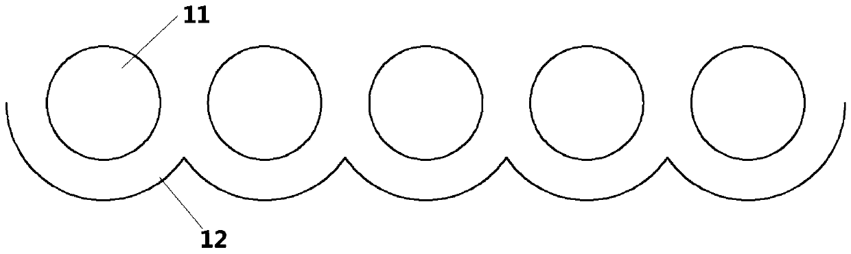
[0053] As preferred, such as image 3 As shown, the heat collecting tubes 11 are multiple in parallel, and the lower part of each heat collecting tube 11 corresponds to a reflector 12, and the ends of the reflectors 12 are connected to form an integral structure. Through the above structure, more heat collecting tubes can be...


PUM


Abstract

The invention provides a trough solar heat collection system, which includes a heat collector, the heat collector includes a heat collection tube and a reflector, the heat collection tube absorbs solar energy, and heats the water in the heat collection tube. It is characterized in that the heat collection tube is set A plurality of stabilizing devices, along the flow direction of the fluid in the heat collecting tube, the spacing between the stabilizing devices becomes smaller and smaller. The present invention can maximize the heat exchange effect through the above arrangement.

Description

technical field [0001] The invention belongs to the field of solar energy, in particular to a solar heat collector. Background technique [0002] With the rapid development of modern society and economy, the human demand for energy is increasing. However, the reserves of traditional energy such as coal, oil, and natural gas continue to decrease and become increasingly scarce, resulting in rising prices. At the same time, the environmental pollution caused by conventional fossil fuels is also becoming more and more serious. These greatly limit the development of society and the improvement of human life quality. . Solar thermal conversion is a solar energy utilization method with high energy conversion efficiency and utilization rate and low cost, which can be widely promoted in the whole society. In solar heat utilization devices, the key is to convert solar radiation energy into heat energy, and the device that realizes this conversion is called a solar collector. [000...

Claims


Application Information

Patent Timeline
Patent Type & Authority Patents(China)
IPC IPC(8): F24S10/70F24S23/70F24S50/00
CPCF24S10/70F24S23/70F24S50/00Y02E10/44
Inventor 不公告发明人
Owner 山东九泽换热系统有限公司
Why Eureka
Try Eureka