
Fire hose drying device based on solution dehumidification and exhaust gas heat recycling

A technology for heat recovery of flue gas and fire hose, which is applied in drying gas arrangement, progressive dryer, drying room/container, etc., can solve the problems of moldy rot, fire hose unable to be dried in time, unable to dry, etc.

Pending Publication Date: 2019-03-19
QINGDAO TECHNOLOGICAL UNIVERSITY
View PDF6 Cites 0 Cited by
  • Summary
  • Abstract
  • Description
  • Claims
  • Application Information

AI Technical Summary

Problems solved by technology

[0003] The present invention aims at the problem that the fire hose cannot be dried in time after use and is prone to mildew and rot, and provides a fire hose drying device with simple structure and rapid drying by heat energy
The invention solves the problem that the fire hose cannot be dried in a short time after use, and at the same time facilitates the maintenance of the fire hose after use by the fire company, prolonging the service life of the fire hose

Method used


Image

  • Fire hose drying device based on solution dehumidification and exhaust gas heat recycling
  • Fire hose drying device based on solution dehumidification and exhaust gas heat recycling
  • Fire hose drying device based on solution dehumidification and exhaust gas heat recycling

Examples


Embodiment Construction

[0011] A fire hose drying device based on solution dehumidification and flue gas heat recovery according to the present invention will be further described below in combination with illustrations.

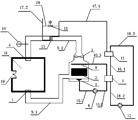
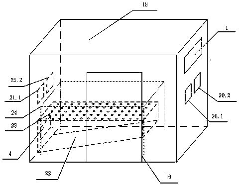
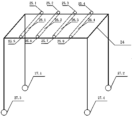
[0012] Such as figure 1 , figure 2 , image 3 As shown, a fire hose drying device based on solution dehumidification and flue gas heat recovery, including: return air outlet 1, absorber 2, fan 3, air inlet 4, lithium bromide dilute solution collector 5, solution pump 6, generator 7. Lithium bromide concentrated solution nozzle 8, air pipe 9, solution pipe 10, gas boiler 11, hot water pump 12, heat recovery device 13, thermometer 14, electronic bypass ventilation valve 15, water pipe 16, flue gas pipe 17, drying chamber 18, Personnel access door 19, fire hose inlet 20, fire hose outlet 21, plenum box 22, orifice plate 23, bracket 24, bearing 25, steel pipe 26, wheel 27, flue gas bypass pipe 28.

[0013] A fire hose drying device based on solution dehumidification and flue gas he...


PUM


Abstract

The invention discloses a fire hose drying device based on solution dehumidification and exhaust gas heat recycling. The fire hose drying device comprises a return air inlet, an air pipe, an absorbingmachine, a draught fan, an air inlet, a drying chamber, a lithium bromide dilute solution collecting machine, a solution pipe, a solution pump, a generator, a lithium bromide concentrated solution spraying nozzle, a gas fired boiler, a hot water pump, a heat recycling device, a thermometer, an electronic bypass air valve, a water pump, an exhaust gas pipe, and an exhaust gas bypass pipe. The drying chamber comprises an air inlet, a return air inlet, a fire hose inlet, a fire hose outlet, a personnel entering exiting door, and a working table.When moisture content of circulating air in the drying chamber increases, and under action of the draught fan, the circulating air enters the absorbing machine, heat-moisture exchange occurs between the circulating air and the lithium bromide concentrated solution, the circulating air is dried and heated and is secondarily heated by the heat recycling device, and enters the drying chamber through the air inlet to dry the fire hose. The problem that the fire hose cannot be dried for a short time after use is solved, maintenance of fire hoses of fire fighting companies after use is facilitated, and the service life of the fire hoses is prolonged.

Description

technical field [0001] The invention relates to a fire hose drying device based on solution dehumidification and flue gas heat recovery, which is used in the drying field of fire hose. Background technique [0002] As an important firefighting equipment tool, the fire hose is used to transport high-pressure water or foam and other flame-retardant liquids. The inside of the fire hose is rubber and the outside is nylon cloth. Due to the working environment of the fire hose, there is a lot of water on the surface of the fire hose after use. If the fire hose is not dried in time, it will easily lead to mold and rot of the hose, shorten the service life of the fire hose, and not Conducive to the normal use of fire hose. At the same time, the temperature of the hot air generated by the drying device at this stage is too high, and the rubber inside the fire hose is easily damaged due to high temperature. However, the present invention proposes a fire-fighting hose drying device ...

Claims


Application Information

Patent Timeline
Patent Type & Authority Applications(China)
IPC IPC(8): F26B13/10F26B21/00F26B21/04F26B21/08F26B25/06F26B25/12F25B15/06
CPCF25B15/06F26B13/10F26B21/004F26B21/04F26B21/08F26B25/06F26B25/12Y02B30/62Y02A30/27Y02P70/10
Inventor 刘龙李崇崔国峰魏佳雪邢秀强
Owner QINGDAO TECHNOLOGICAL UNIVERSITY
Learn More