Bending and anti-cracking performance testing device and testing method
A test device and crack resistance technology, applied in the field of testing, can solve the problems of the test piece affecting the test accuracy, affecting the test accuracy, etc.
- Summary
- Abstract
- Description
- Claims
- Application Information
AI Technical Summary
Problems solved by technology
Method used
Image
Examples
Embodiment 1
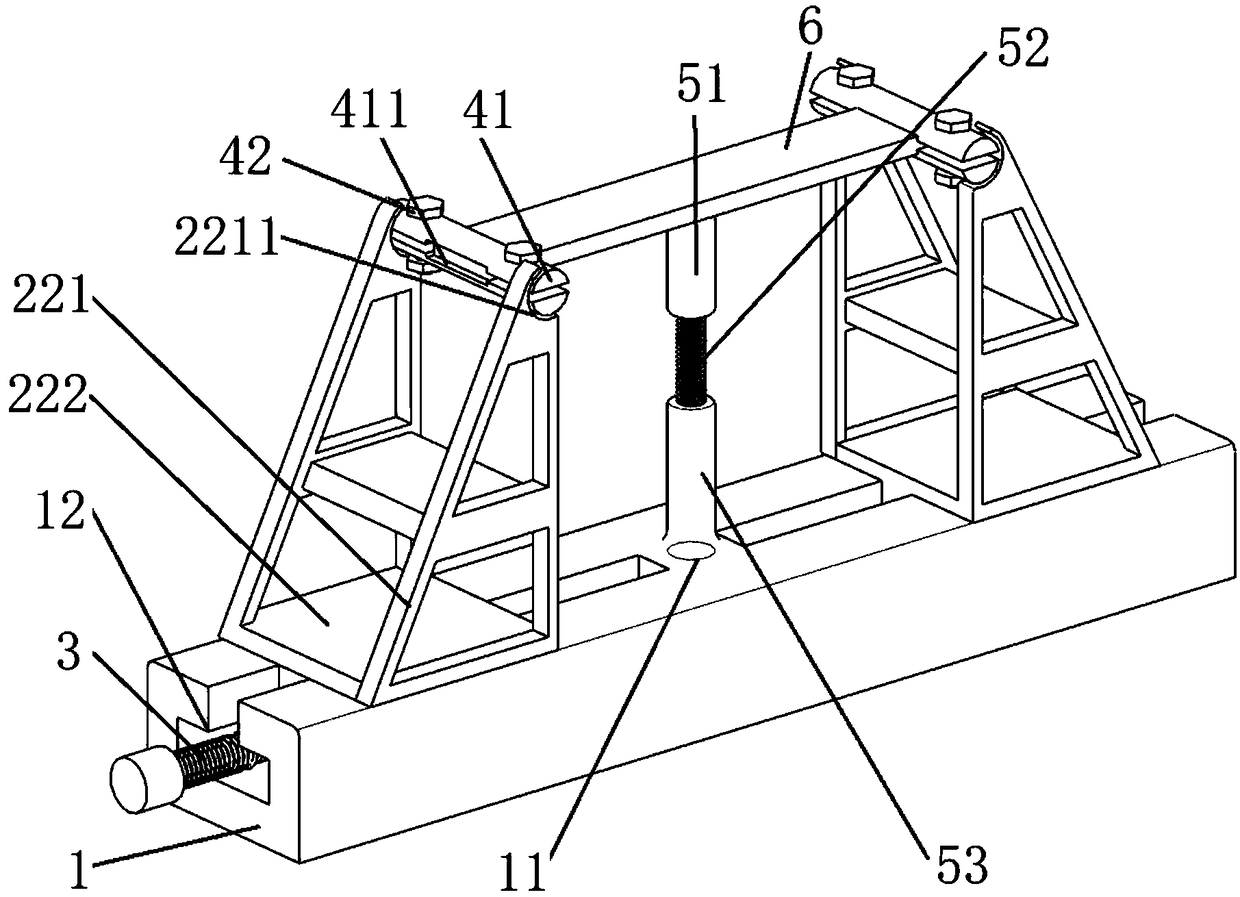
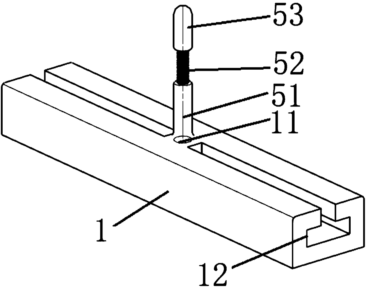
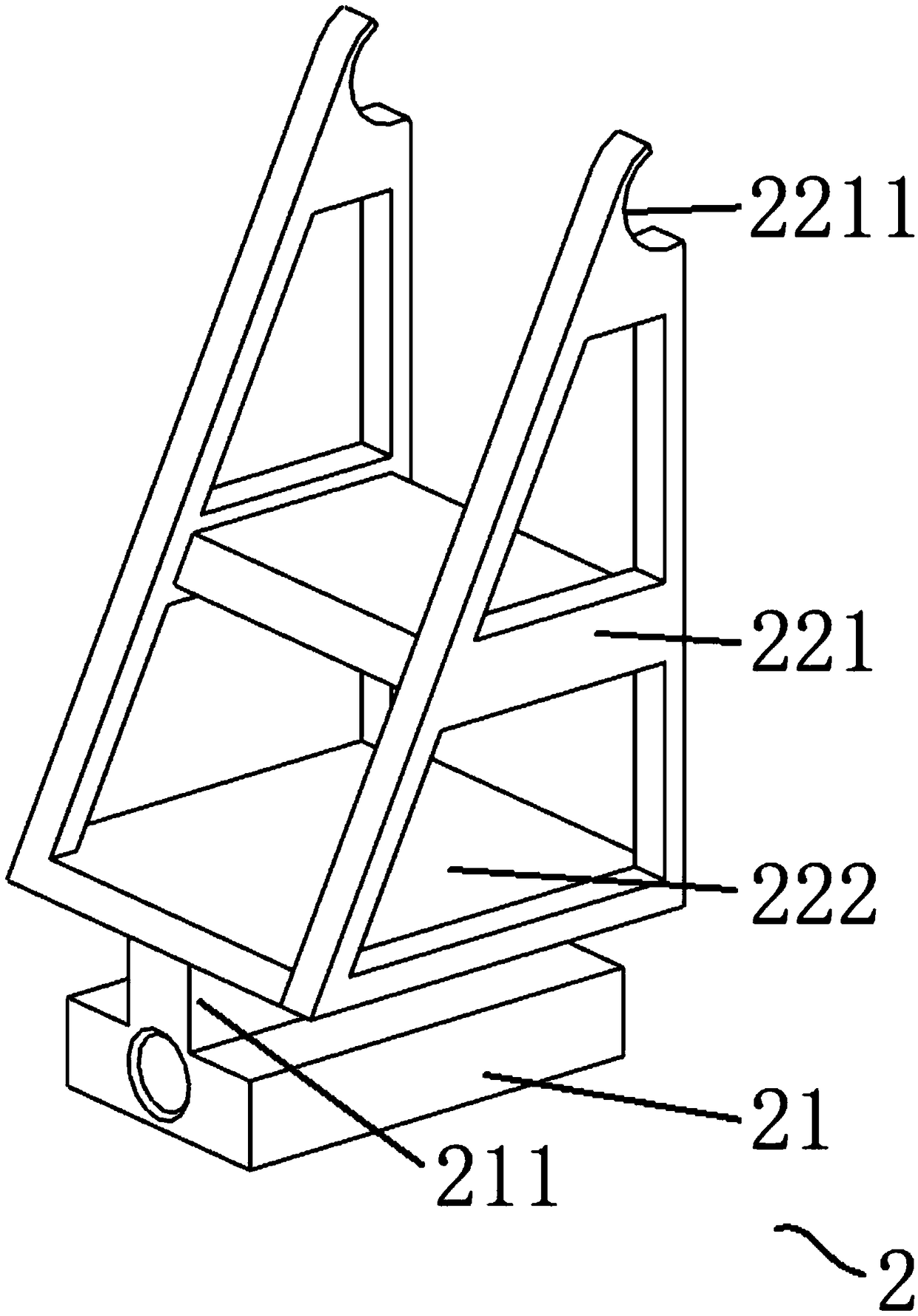
[0074] This embodiment provides a bending crack resistance testing device, which includes: a base 1, a force applying mechanism, at least one pair of clamping mechanisms, a bending guiding mechanism and an image processing system. The clamping mechanism is used to clamp the test piece 6; the force applying mechanism includes a pair of supporting components 2 and a driving component, wherein the supporting component 2 is movably arranged on the base 1 to support and fix the clamping mechanism; the driving component drives the supporting component 2 to move ; The bending guide mechanism is fixed on the base 1, and one end thereof abuts against the side surface of the test piece 6 to limit the bending of the test piece 6 in the direction where the bending guide mechanism is located. It should be noted that the test piece 6 in this embodiment is a plate-shaped resin material test piece. Of course, it can also be a test piece 6 made of other materials.
[0075] Such as figure 1 a...
Embodiment 2
[0085] This embodiment provides a test method for a fracture test using the bending crack resistance test device in Example 1, which includes the following steps in sequence:
[0086] S1: Assemble the test piece 6 in the clamping mechanism: specifically, first place the test piece 6 in the clamping space 411 formed by the semi-cylindrical body 41, and then figure 1 and Figure 4 Bolt 42 is shown locked.
[0087] S11: Adjust the length of the bending guide mechanism so that it abuts against the surface of the test piece 6: specifically, adjust the length of the bending guide mechanism by adjusting the screw 52 .
[0088] S2: The driving component such as a motor or manpower drives the supporting component 2 to move closer, so that the test piece 6 in the clamping mechanism is bent until it breaks;
[0089] Step S3 carried out simultaneously with step S2: the image acquisition device captures and collects a number of bending shape images of the test piece 6 at different moment...
PUM
 Abstract
Description
Claims
Application Information
 - R&D
- Intellectual Property
- Life Sciences
- Materials
- Tech Scout
- Unparalleled Data Quality
- Higher Quality Content
- 60% Fewer Hallucinations
Browse by: Latest US Patents, China's latest patents, Technical Efficacy Thesaurus, Application Domain, Technology Topic, Popular Technical Reports.
© 2025 PatSnap. All rights reserved.Legal|Privacy policy|Modern Slavery Act Transparency Statement|Sitemap|About US| Contact US: help@patsnap.com


