Device and method for life prediction of rail transit converter

A rail transit and life prediction technology, applied in the field of rail transit, can solve problems such as fixed outbreaks, communication interruptions, and high failure rates, and achieve the effects of reducing the probability of failure, improving reliability, and ensuring reliability

Active Publication Date: 2021-01-29
CSR ZHUZHOU ELECTRIC LOCOMOTIVE RES INST
View PDF15 Cites 0 Cited by
  • Summary
  • Abstract
  • Description
  • Claims
  • Application Information

AI Technical Summary

Problems solved by technology

Screening statistics from these fault information and further decomposing, it is found that chassis fans generally have a service life, especially fan motors. Generally speaking, the service life is strongly related to ambient temperature and vibration. The failure rate is high; with the passage of time and the harshness of the vibration environment, the communication interruption caused by the loose structure of the product box has become a typical failure, and it has a trend of increasing year by year and a fixed outbreak; electrolytic capacitors Affected by the operating environment, the locomotives operating in the Northwest and tropical regions for a long time have frequent extreme high temperatures. The operating environment of capacitors is more stringent than the requirements of the iron standard. The failure of capacitors after long-term use under high temperature conditions has become an urgent problem. Common quality problems; through the accumulation of application experience of relay products, it is found that some inserted materials, sudden changes in temperature or severe vibration for a certain period of time will cause cracking of solder joints, affecting the correctness of relay actions, resulting in field operation failures; FLASH memory is in use It is found that continuous work at high temperature is prone to failure. After reliability high temperature test verification, when the device is at a certain high temperature, it will cause typical failures such as bit flips

Method used


Image

  • Device and method for life prediction of rail transit converter
  • Device and method for life prediction of rail transit converter
  • Device and method for life prediction of rail transit converter

Examples


Embodiment Construction

[0025] The present invention will be further described below in conjunction with the accompanying drawings and specific embodiments.

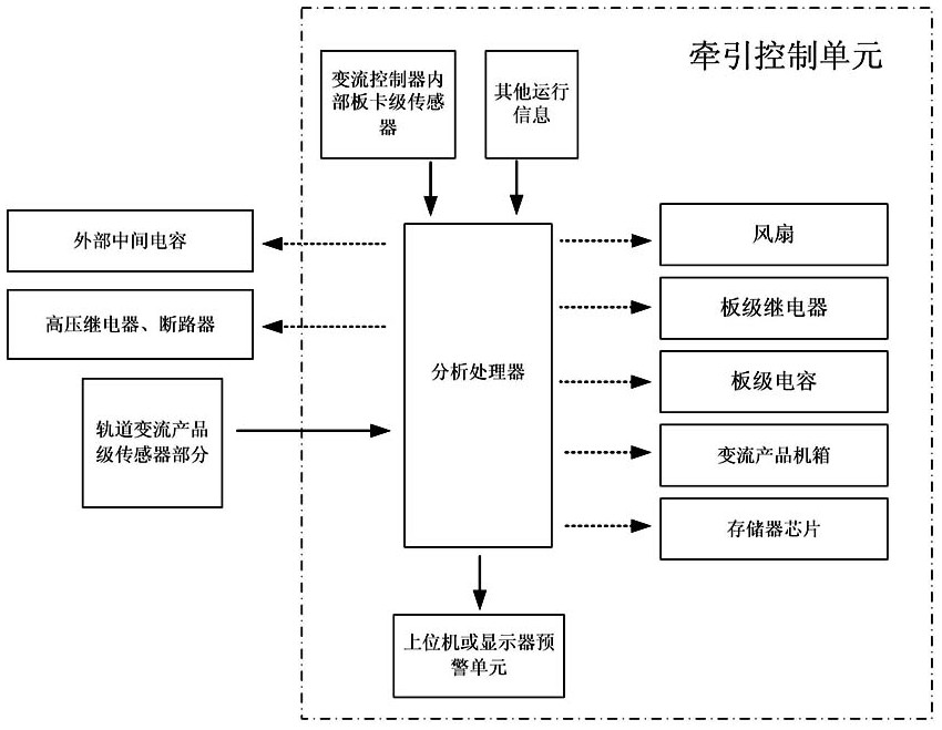
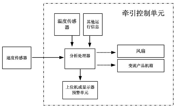
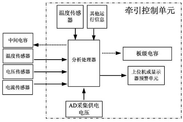
[0026] Such as Figure 1 to Figure 5 As shown, the rail transit converter life prediction device of this embodiment includes an analysis unit, an internal board-level sensor unit of the converter controller, and a rail converter product-level sensor unit; the analysis unit is connected to the internal board of the converter controller respectively. The level sensor unit is connected with the rail conversion product level sensor unit, and is used to analyze and process the signals collected by the board level sensor unit inside the converter controller and the rail conversion product level sensor unit to analyze the components in the rail converter. life expectancy. The life prediction device of the rail transit converter of the present invention is based on the locomotive sensor network in the existing rail transit, monitors various data durin...


PUM


Abstract

The invention discloses a life prediction device for a rail transit converter, which comprises an analysis unit, a board-level sensor unit inside a converter controller, and a track converter product-level sensor unit; The sensor unit is connected to the rail converter product-level sensor unit, and is used to analyze and process the signals collected by the board-level sensor unit inside the converter controller and the rail converter product-level sensor unit to determine the life of each component in the rail converter. Make predictions. The invention also discloses a prediction method. When the rail transit converter is in normal operation, the board-level sensor unit inside the converter controller and the track converter product-level sensor unit collect the data of the corresponding components and send them to the analysis unit for analysis. The unit classifies the collected data and predicts the life of each component in the rail converter. Both the predicting device and the predicting method of the present invention have the advantages of high degree of automation and high reliability.

Description

technical field [0001] The invention mainly relates to the field of rail transit technology, in particular to a device and method for predicting the life of a rail transit converter. Background technique [0002] Rail transit converter products enter into the product bathtub curve when they are put into operation. However, with the passage of time and different complex application environments, the time for a part-life device to reach the end of its life cycle is also different. For example, the operating environment of freight locomotives is obviously worse than that of passenger sports cars. According to actual statistics, the number of failures is also more in the former than in the latter. Screening statistics from these fault information and further decomposing, it is found that chassis fans generally have a service life, especially fan motors. Generally speaking, the service life is strongly related to ambient temperature and vibration. The failure rate is high; wit...

Claims


Application Information

Patent Timeline
Patent Type & Authority Patents(China)
IPC IPC(8): G01R31/00
CPCG01R31/003G01R31/008
Inventor 吕阳刘可安尚敬许峻峰倪大成刘良杰李雪江戴计生李泽泉付伟明
Owner CSR ZHUZHOU ELECTRIC LOCOMOTIVE RES INST
Why Eureka
Try Eureka