Automatic welding device, clamping robot and automatic welding method

A welding robot and automatic welding technology, applied in welding equipment, welding equipment, auxiliary welding equipment, etc., can solve the problems of high work intensity, energy consumption, and long time consumption of workers, so as to reduce the work intensity of workers and realize welding Effects of automation and productivity improvement

Active Publication Date: 2019-03-19
SHENZHEN A&E INTELLIGENT TECH INST CO LTD
View PDF7 Cites 5 Cited by
  • Summary
  • Abstract
  • Description
  • Claims
  • Application Information

AI Technical Summary

Problems solved by technology

Therefore, when performing manual intervention clamping, it takes a long time and consumes too much energy of workers
[0004] At present, the manual welding of steel mesh has disadvantages such as high work intensity, harsh working environment, long welding time, and waste of labor.

Method used


Image

  • Automatic welding device, clamping robot and automatic welding method
  • Automatic welding device, clamping robot and automatic welding method
  • Automatic welding device, clamping robot and automatic welding method

Examples


Embodiment Construction

[0015] This application provides an automatic welding equipment, clamping robot and automatic welding method. In order to make the purpose, technical solution and technical effect of this application clearer and clearer, the application will be further described in detail below, and it should be understood that the specific implementation regulations described here It is only used to explain the application, not to limit the application.

[0016] The automatic welding equipment, clamping robot and automatic welding method proposed by the present application will be described in detail below with reference to the accompanying drawings.

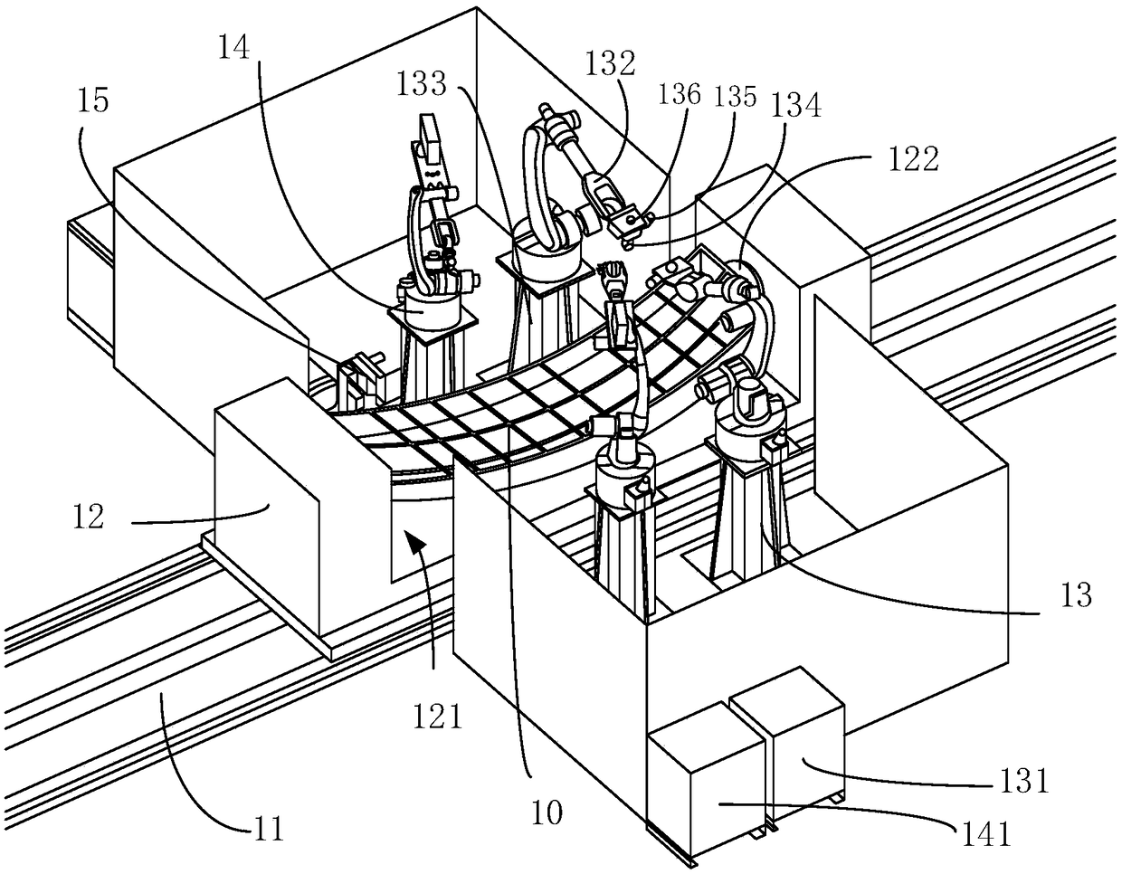
[0017] see figure 1 , figure 1 It is a structural schematic diagram of an embodiment of the automatic welding equipment of the present application. The automatic welding equipment of this embodiment includes a code material mold 12, a clamping robot 13, a welding robot 14, a welding machine (not marked) and a gun cleaner 15. Through the coope...


PUM


Abstract

The invention relates to an automatic welding device, a clamping robot and an automatic welding method. The automatic welding device comprises: a code material tire (12), which is used for placing cross-shaped transverse steel bars and longitudinal steel bars to be welded materials, wherein the transverse steel bars and longitudinal steel bars form a a reinforcing mesh (10), a clamping robot (13)for judging whether there is a gap between the transverse reinforcing bars and the longitudinal reinforcing bars, and clamping the transverse reinforcing bars and the longitudinal reinforcing bars having the gap so as to be in close contact with each other, and a welding robot ( 14) for welding the transverse reinforcing bars and longitudinal reinforcing bars that are close to each other.

Description

technical field [0001] The present application relates to the field of automatic welding, in particular to an automatic welding device, a clamping robot and an automatic welding method. Background technique [0002] Many building structures such as roofs, exterior walls, and bridges need to bend steel bars and combine them into steel meshes for welding and installation during construction. However, in the prior art, the welding of the steel mesh is done manually. When manual welding is performed, it is necessary to put the assembled steel mesh into the fixture before welding. [0003] However, the steel mesh put into the fixture is not always in a state that can be directly welded, and gaps will occur between the reinforcing bars at some positions to be welded in the steel mesh to block the welding. For positions to be welded with gaps, manual intervention and clamping are required, and because the steel mesh is large, there are many positions to be welded on the steel mesh...

Claims


Application Information

Patent Timeline
Patent Type & Authority Applications(China)
IPC IPC(8): B23K37/00B23K37/04B23K31/00
CPCB23K31/00B23K37/00B23K37/0443
Inventor 赫少华王磊
Owner SHENZHEN A&E INTELLIGENT TECH INST CO LTD
Why Eureka
Try Eureka