Steel bar cutting machine for bridge construction

A steel bar cutting machine and bridge construction technology, applied in the direction of cleaning methods and appliances, smoke and dust removal, chemical instruments and methods, etc., can solve problems such as inconvenient use, achieve the effects of reducing the number of uses, easy removal of debris, and improving cutting efficiency

Active Publication Date: 2019-03-22
黑龙江省龙建路桥第五工程有限公司
View PDF8 Cites 6 Cited by
  • Summary
  • Abstract
  • Description
  • Claims
  • Application Information

AI Technical Summary

Problems solved by technology

[0003] The purpose of the present invention is to provide a steel bar cutting machine for bridge construction, which has the advantage of being easy to use and solves the problem that common steel bar cutting machines for bridge construction are not easy to use

Method used


Image

  • Steel bar cutting machine for bridge construction
  • Steel bar cutting machine for bridge construction

Examples


no. 1 approach

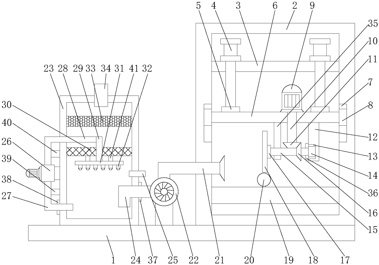
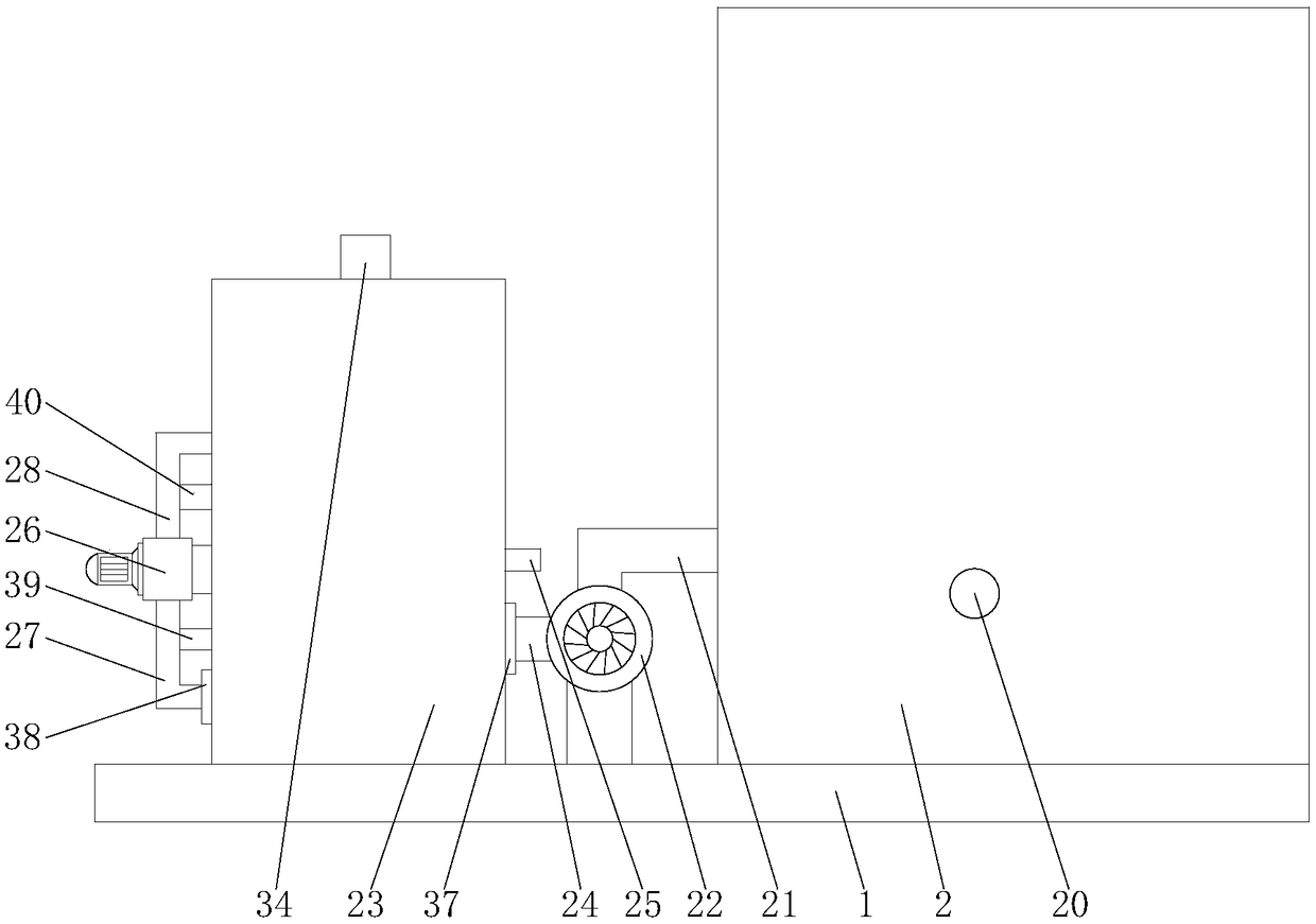
[0017] First implementation: see Figure 1-2, a steel bar cutting machine for bridge construction, comprising a bottom plate 1, the right side of the top of the bottom plate 1 is fixedly connected with an organic casing 2, the inner wall of the casing 2 is fixedly connected with a fixed plate 3, and the top of the fixed plate 3 is fixedly connected with two Cylinder 4, the bottom of the cylinder 4 runs through the fixed plate 3 and extends to the outside, the bottom of the cylinder 4 is fixedly connected with the connecting block 5, the bottoms of the two connecting blocks 5 are fixedly connected by the sliding plate 6, and the left and right of the inner wall of the casing 2 slide correspondingly The position of the plate 6 is provided with a chute 7, the inner wall of the chute 7 is slidably connected with a slider 8, and the two sliders 8 are fixedly connected by the sliding plate 6, and the top of the sliding plate 6 is located at the two connecting blocks 5 A cutting moto...

no. 2 approach

[0020] The second embodiment: as shown in claim 1, a steel bar cutting machine for bridge construction, comprising a bottom plate 1, the right side of the top of the bottom plate 1 is fixedly connected with an organic casing 2, and the inner wall of the casing 2 is fixedly connected There is a fixed plate 3, the top of the fixed plate 3 is fixedly connected with two cylinders 4, the bottom of the cylinder 4 runs through the fixed plate 3 and extends to the outside, the bottom of the cylinder 4 is fixedly connected with a connecting block 5, the two The bottom of each connection block 5 is fixedly connected by a sliding plate 6, and the left and right sides of the inner wall of the casing 2 corresponding to the position of the sliding plate 6 are all provided with a chute 7, and the inner wall of the chute 7 is slidably connected with a slider 8. The two sliders 8 are fixedly connected by a sliding plate 6, the top of the sliding plate 6 and between the two connecting blocks 5 a...


PUM


Abstract

The invention discloses a steel bar cutting machine for bridge construction. The steel bar cutting machine comprises a bottom plate, wherein the right side of the top of the bottom plate is fixedly connected with a shell; the inner wall of the shell is fixedly connected with a fixing plate; the top of the fixing plate is fixedly connected with two cylinders; the bottom portion of each cylinder penetrates through the fixing plate to extend outside of the fixing plate; the bottom of each cylinder is fixedly connected with a connecting block; the bottoms of the two connecting blocks are fixedly connected through a sliding plate; and sliding slots are formed in the position, corresponding to the sliding plate, of the left side and the right side of the inner wall of the shell. According to thesteel bar cutting machine for bridge construction, a dust suction pipe, a fan, a dedusting box, a dedusting pipe, a water injection pipe, a water pump, a water outlet pipe, a water inlet pipe, a water pipe, a filter plate, a water spray pipe, a nozzle, a water absorption plate and an exhaust pipe are mutually cooperated, so that the problem of inconvenient use of common steel bar cutting machinesfor bridge construction is solved; the steel cuttings are handled when steel bars are cut, so that the cutting efficiency is improved while the harm caused by the steel cuttings to the human body isavoided; and great convenience is brought to users.

Description

technical field [0001] The invention relates to the technical field of bridge construction, in particular to a steel bar cutting machine for bridge construction. Background technique [0002] According to the design content of bridge construction, the process of building bridges mainly refers to bridge construction technology, construction organization, construction management, construction quality, etc. Bridge construction needs to use steel bars, and steel bars need to be cut during use. Steel bar cutting machine is a A tool used for cutting steel bars. The steel bar cutting machine is one of the indispensable equipment for steel bar processing. It is mainly used for cutting steel bars at fixed lengths in housing construction, bridges, tunnels, power stations, and large-scale water conservancy projects. Generally, there are fully automatic steel bar cutting machines and semi-automatic steel bar cutting machines. The fully automatic cutting machine is also called the elect...

Claims


Application Information

Patent Timeline
Patent Type & Authority Applications(China)
IPC IPC(8): B21F11/00B08B15/04
CPCB08B15/04B21F11/00
Inventor 韩超
Owner 黑龙江省龙建路桥第五工程有限公司
Why Eureka
Try Eureka