
Multi-shaft drilling machine

A multi-axis drilling machine and rotating shaft technology, which is applied to the parts of boring machine/drilling machine, boring/drilling, drilling/drilling equipment, etc., can solve unreliable clamping, low processing efficiency, inaccurate shaft tube positioning, etc. problems, to avoid excessive damage, reduce intermediate processes, and ensure the effect of service life

Active Publication Date: 2019-03-22
重庆全能电器有限公司
View PDF5 Cites 1 Cited by
  • Summary
  • Abstract
  • Description
  • Claims
  • Application Information

AI Technical Summary

Problems solved by technology

[0003] For the processing of pipe parts, the existing drilling machine usually sets a fixed station for the workpiece, and then sets a drill station at the corresponding position, and then controls the drill to drill the workpiece through the control part. Such a drilling machine tool, once Only one workpiece can be processed, which is time-consuming, labor-intensive and low-efficiency
Moreover, many tube and shaft parts require high precision for drilling, but at present, the positioning of the shaft tube is often inaccurate during drilling, and the clamping is not reliable, resulting in low machining accuracy of the shaft tube and unable to meet the working requirements.

Method used


Image

  • Multi-shaft drilling machine
  • Multi-shaft drilling machine

Examples


Embodiment Construction

[0018] The following is further described in detail through specific implementation methods:

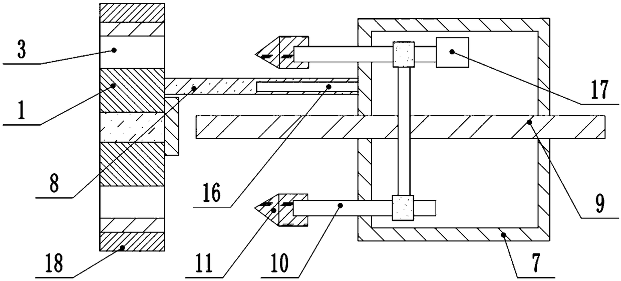
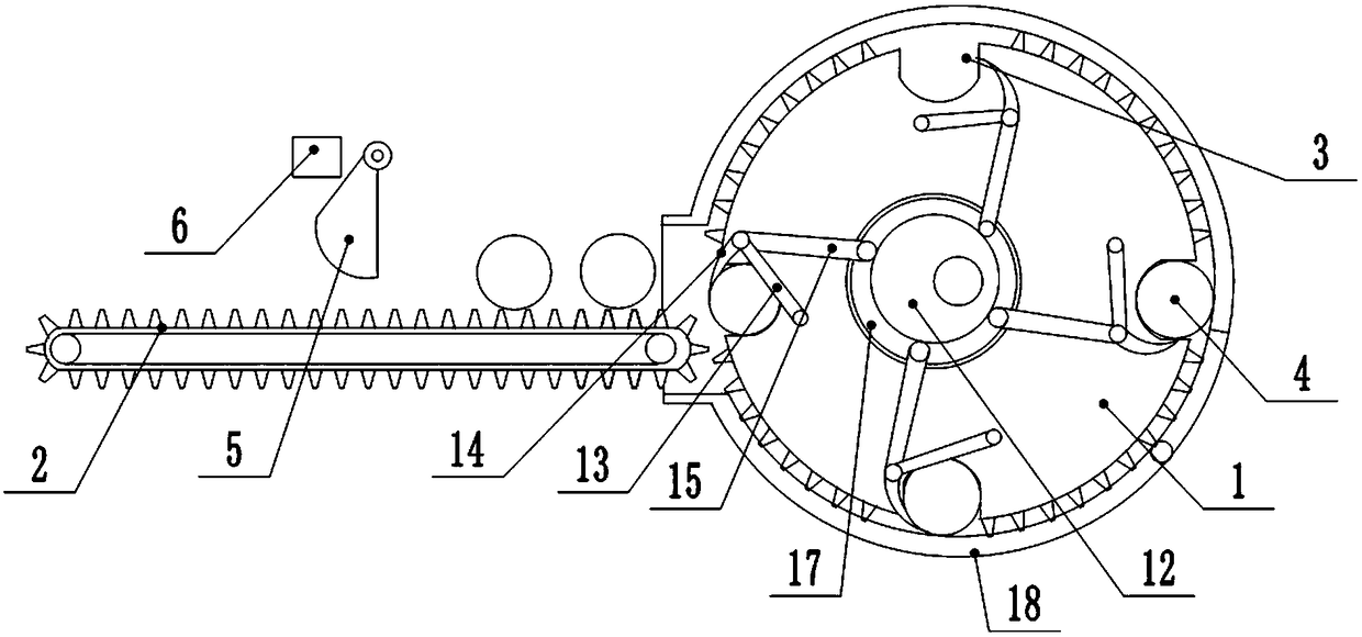
[0019] The reference signs in the drawings of the description include: positioning gear 1, conveyor belt 2, gap 3, parts 4, limit plate 5, fixed block 6, placement box 7, connecting rod 8, threaded rod 9, rotating shaft 10, drill bit 11, Eccentric wheel 12, guide rod 13, ratchet 14, pull bar 15, chute 16, second motor 17, baffle plate 18.

[0020] Examples are attached figure 1 Shown: a multi-axis drilling machine, including a frame, a positioning mechanism and a drilling mechanism are arranged on the frame, and the positioning mechanism is located on the left side of the drilling mechanism.

[0021] Such as figure 2 As shown, the positioning mechanism includes a conveyor belt 2 , a positioning gear 1 and an eccentric wheel 12 located on the right side of the conveyor belt 2 .

[0022] The conveyor belt 2 rotates circularly around two runners, and the runners are connected to the...


PUM


Abstract

The invention belongs to the technical field of machining, and particularly relates to a multi-shaft drilling machine. The multi-shaft drilling machine comprises a machine frame, a positioning mechanism and a drilling mechanism are arranged on the machine frame, the positioning mechanism comprises a conveyor belt and a positioning gear, and sawteeth are arranged on the surface of the conveyor belt. Arc-shaped notches are formed in the edge of the positioning gear, and the positioning gear is connected with a first power source for driving the positioning gear to rotate. The drilling mechanismcomprises a placing box, a thread rod and a connecting rod, and a plurality of rotating shafts are rotatably connected to the side wall of the placing box. Second power sources for driving the rotating shafts to rotate are connected to the end on which the rotating shafts are located in the placing box, and drill bits are connected to the other end on which the rotating shafts are located in the placing box. The thread rod is fixedly connected with the machine frame, and the connecting rod is slidably connected with the placing box. According to the technical scheme, cylindrical workpieces areenabled to fall into the notches of the positioning gear through the rotation of the positioning gear, the workpieces are automatically fixed, and then the multiple workpieces are drilled at the sametime by using the drilling mechanism.

Description

technical field [0001] The invention belongs to the technical field of mechanical processing, and in particular relates to a multi-axis drilling machine. Background technique [0002] In the field of mechanical processing technology, it is often necessary to process parts such as drilling. Drilling machines are general-purpose machine tools with a wide range of uses, and are widely used in the drilling of various parts. [0003] For the processing of pipe parts, the existing drilling machine usually sets a fixed station for the workpiece, and then sets a drill station at the corresponding position, and then controls the drill to drill the workpiece through the control part. Such a drilling machine tool, once Only one workpiece can be processed, which is time-consuming, labor-intensive, and processing efficiency is low. Moreover, many tube and shaft parts require high precision for drilling, but at present, the positioning of the shaft tube is often inaccurate during drilli...

Claims


Application Information

Patent Timeline
IPC IPC(8): B23B39/16B23B47/16B23Q7/00B23Q7/02
CPCB23B39/161B23Q5/10B23Q7/00B23Q7/003B23Q7/02
Inventor 左陶
Owner 重庆全能电器有限公司
Learn More