Automatic PCB punching and feeding equipment capable of stably running

A technology with stable operation and equipment, applied in the field of machinery, can solve the hidden danger of pollution and safety, and can not effectively solve problems such as products

Pending Publication Date: 2019-03-22
SHENZHEN QIANGRUI ELECTRONICS
View PDF17 Cites 4 Cited by
  • Summary
  • Abstract
  • Description
  • Claims
  • Application Information

AI Technical Summary

Problems solved by technology

[0003] According to a PCB adsorption device and PCB feeding equipment announced by Chinese Patent No. CN207716962.U, although this patent solves the problem that the PCB adsorption device often appears when it is facing a stack of PCBs with separators when it absorbs the separators. The problem of absorbing the PCB below together, but the technical solution proposed by the patent cannot effectively solve the problems of product pollution and safety hazards in manual feeding

Method used


Image

  • Automatic PCB punching and feeding equipment capable of stably running
  • Automatic PCB punching and feeding equipment capable of stably running
  • Automatic PCB punching and feeding equipment capable of stably running

Examples


Embodiment Construction

[0028] In order to further illustrate the various embodiments, the present invention provides accompanying drawings, which are part of the disclosure of the present invention, and are mainly used to illustrate the embodiments, and can be used in conjunction with the relevant descriptions in the specification to explain the operating principles of the embodiments, for reference Those of ordinary skill in the art should be able to understand other possible implementations and advantages of the present invention. The components in the figures are not drawn to scale, and similar component symbols are generally used to represent similar components.

[0029] According to the embodiment of the present invention, an automatic punching and feeding device for PCB with stable operation is provided.

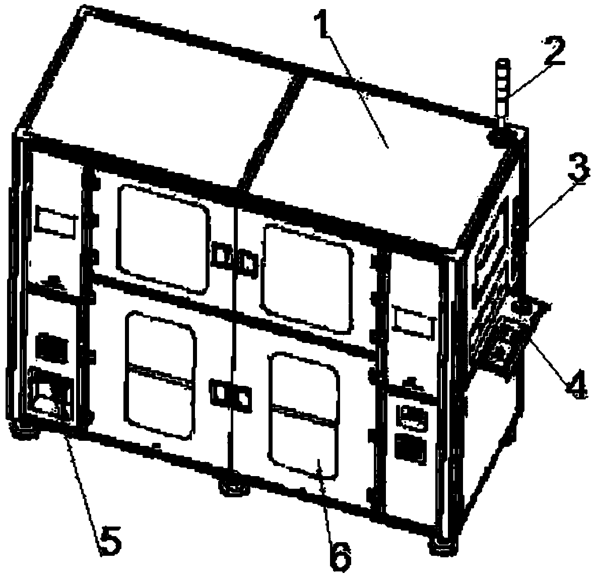
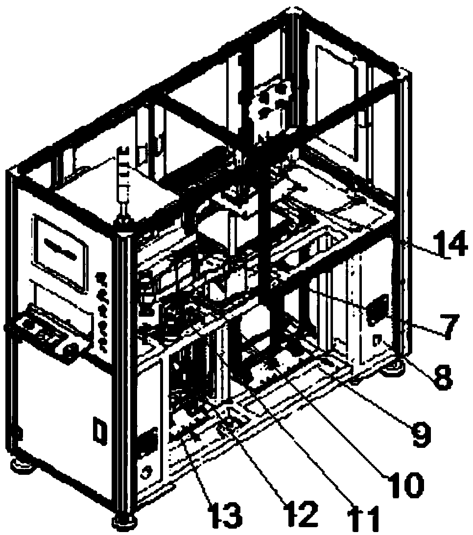
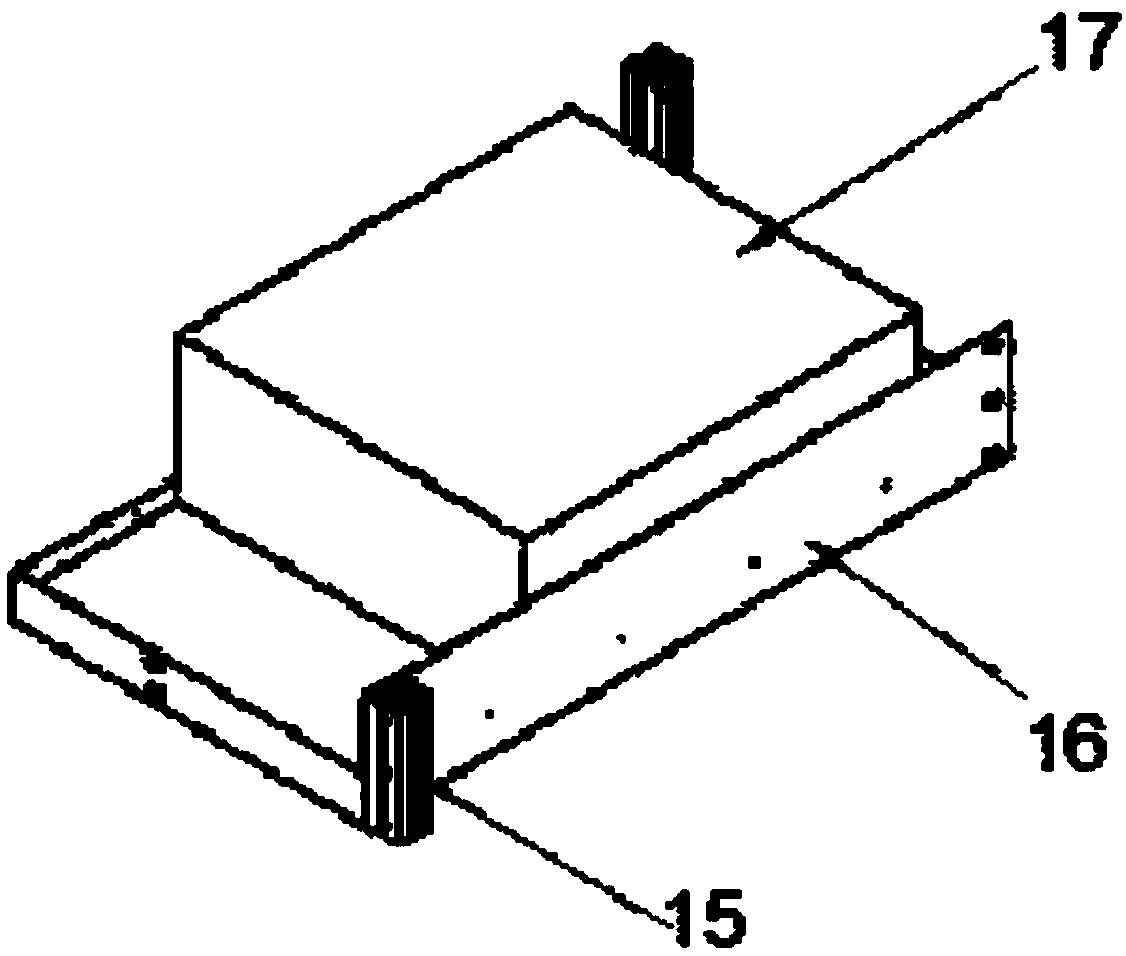
[0030] The present invention is further described in conjunction with accompanying drawing and specific embodiment now, as Figure 1-8 As shown, a stable PCB automatic punching and feeding d...


PUM


Abstract

The invention discloses an automatic PCB punching and feeding equipment capable of stably running. The automatic PCB punching and feeding equipment capable of stably running comprises an equipment body; a three-color lamp is arranged on the edge of one side of the top end of the equipment body; a control button is arranged at the upper end of one side of the equipment body; a control assembly is arranged on the portion, located under the control button, of one side of the equipment body; an air source processing element is arranged on the edge of the bottom of one side of the equipment body; arack protecting cover is arranged on one side of the equipment body; and an industrial control unit fixing assembly, a rack protecting cover assembly, a discharging length and width adjusting assembly, a robot fixture assembly, a lower camera assembly, a lift assembly, a feeding length and width adjusting assembly and a carrying disc transplanting assembly are arranged in the equipment body, thedischarging length and width adjusting assembly is located at the bottom of the interior of the equipment body, and the feeding length and width adjusting assembly is located over the discharging length and width adjusting assembly. The automatic PCB punching and feeding equipment capable of stably running has the beneficial effects that the equipment universality is high, products with differentspecifications can be met, discharging is precise, and the different products can be quickly switched.

Description

technical field [0001] The invention relates to the field of mechanical technology, in particular to a PCB automatic punching and feeding device with stable operation. Background technique [0002] PCB (Printed Circuit Board), the Chinese name is printed circuit board, also known as printed circuit board, is an important electronic component, a support for electronic components, and a carrier for electrical connections of electronic components. Because it is made by electronic printing, it is called a printed circuit board. At present, the punching of PCB products in the industry is mostly done manually, which is easy to cause product pollution and injury. At the same time, the movement of the punching machine will cause safety hazards to personnel. [0003] According to a PCB adsorption device and PCB feeding equipment announced by Chinese Patent No. CN207716962.U, although this patent solves the problem that the PCB adsorption device often appears when it absorbs the separ...

Claims


Application Information

Patent Timeline
Patent Type & Authority Applications(China)
IPC IPC(8): B65G49/06
CPCB65G49/061
Inventor 尹高斌刘刚
Owner SHENZHEN QIANGRUI ELECTRONICS
Why Eureka
Try Eureka