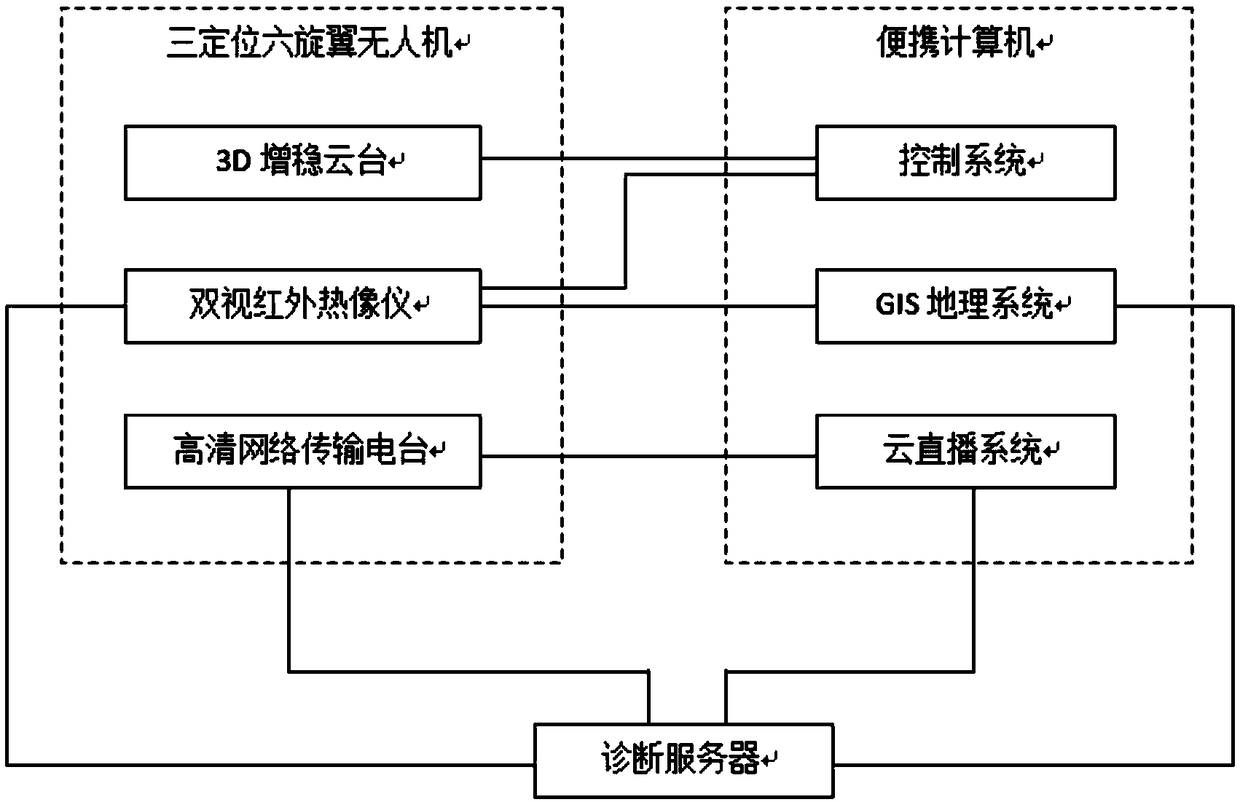
Heat distribution pipeline detection system based on visible light and infrared thermal imaging

An infrared thermal imaging and thermal pipeline technology, which is applied in pipeline systems, mechanical equipment, gas/liquid distribution and storage, etc., can solve the problems of low infrared image resolution, low efficiency, low accuracy of collected data, etc. The effect of accurate detection

Inactive Publication Date: 2019-03-22
天津市津能滨海热电有限公司
View PDF4 Cites 14 Cited by
  • Summary
  • Abstract
  • Description
  • Claims
  • Application Information

AI Technical Summary

Problems solved by technology

The traditional infrared thermal imaging detection methods are as follows: 1. Using a handheld thermal imager, manual walking inspection, the detection range is small, the efficiency is low, and the fault point confirmation process is complicated
2. The simple airborne infrared thermal imager transmits the video signal of the thermal imager to the ground through the UAV image transmission equipment, which improves the detection efficiency, but it cannot do on-site fault analysis, and needs to do post-analysis of images and videos. To confirm the fault point, due to the low resolution of the infrared image and the lack of GPS location information, the confirmed fault point cannot be accurately located, and it takes a lot of time to analyze and judge the location of the fault point. For an efficient UAV detection platform, fault location is a Very weak link that greatly reduces the usability of new detection techniques
There is no pipeline navigation for UAV flight, relying on manual blind flight, the accuracy of data collection is not high

Method used


Image

  • Heat distribution pipeline detection system based on visible light and infrared thermal imaging

Examples


Embodiment Construction

[0017] In describing the present invention, it should be understood that the terms "center", "longitudinal", "transverse", "upper", "lower", "front", "rear", "left", "right", " The orientations or positional relationships indicated by "vertical", "horizontal", "top", "bottom", "inner" and "outer" are based on the orientations or positional relationships shown in the drawings, and are only for the convenience of describing the present invention and Simplified descriptions, rather than indicating or implying that the device or element referred to must have a particular orientation, be constructed and operate in a particular orientation, and thus should not be construed as limiting the invention. In addition, the terms "first", "second", etc. are used for descriptive purposes only, and should not be understood as indicating or implying relative importance or implicitly specifying the quantity of the indicated technical features. Thus, a feature defined as "first", "second", etc. ...


PUM


Abstract

The invention discloses a heat distribution pipeline detection system based on visible light and infrared thermal imaging. A double-vision infrared thermal imager, a 3D autostable pan and tilt head and a high-definition network transmission radio station are mounted on a three-positioning six-rotor unmanned aerial vehicle, the three-positioning six-rotor unmanned aerial vehicle provides power forthe double-vision infrared thermal imager, the 3D autostable pan and tilt head and the high-definition network transmission radio station, high-precision positioning can be achieved, flight routes canbe planned, and flying tracks can be stored; a mobile portable computer provides an operation environment for a control system, a GIS geographic system and a cloud live system; the 3D autostable panand tilt head is connected with the control system, the double-vision infrared thermal imager is correspondingly connected with the control system, the GIS geographic system and a diagnosis server, the diagnosis server is further connected with the GIS geographic system, the high-definition network transmission radio station and the cloud live system, and the high-definition network transmission radio station is connected with the cloud live system. According to the heat distribution pipeline detection system based on visible light and infrared thermal imaging, the leakage of a heat distribution pipeline can be efficiently and accurately detected, a historical file is established for inspection of the pipeline, and a data basis is provided for overhauling.

Description

technical field [0001] The invention relates to the technical field of thermal pipeline detection, in particular to a thermal pipeline detection system based on visible light and infrared thermal imaging. Background technique [0002] Thermal pipelines are generally laid by direct burial. Once leakage occurs, it will affect normal life heating and industrial production heat, resulting in adverse social impacts and direct economic losses. Therefore, in order to ensure the normal operation of the heat pipe network, leaks should be found in time. At present, the equipment maintenance personnel of most heating companies currently adopt the traditional method of "seeing, touching, and listening", relying on experience, the master's belt, or using a single device for detection, such as a leak meter and a spot thermometer. The hot water pipe network is detected by pressure detection. If the pressure gauge shows a drop in pressure, it indicates that there is a damage leak. However...

Claims


Application Information

Patent Timeline
Patent Type & Authority Applications(China)
IPC IPC(8): F17D5/02
CPCF17D5/02
Inventor 裴连军张金麟张鹏朴成刚朱咏梅童若冰刘焕志屈艳良刘庚
Owner 天津市津能滨海热电有限公司
Why Eureka
Try Eureka