
A single-ended quick-acting main protection method for HVDC transmission lines

A high-voltage direct current transmission and high-voltage direct current technology, which is used in the measurement of electrical variables, current/voltage measurement, fault detection by conductor type, etc. problem to achieve high accuracy

Active Publication Date: 2019-11-26
SOUTHWEST JIAOTONG UNIV
View PDF5 Cites 0 Cited by
  • Summary
  • Abstract
  • Description
  • Claims
  • Application Information

AI Technical Summary

Problems solved by technology

Actual engineering operation experience shows that the existing traveling wave main protection scheme has certain defects: 1) traveling wave protection cannot act on high-impedance grounding faults in the area where the remote grounding resistance of the line is greater than 100Ω; 2) traveling wave protection will Misoperation of non-high-resistance ground faults outside the area, especially metallic ground faults
The reasons for its refusal and malfunction are as follows: When a remote high-resistance grounding fault occurs in the area, due to the large grounding resistance and the long distance of the fault, the electrical parameters used in the calculation of traveling wave protection (traveling wave head voltage, current variation and rate of change) ) in the time domain is significantly reduced, so that the main action criterion cannot be satisfied, and the main protection action cannot be carried out; and when an external metallic ground fault occurs, the calculated value of the traveling wave protection will satisfy Criterion of protection action, main protection maloperation in the area occurs
Therefore, the traveling wave main protection cannot correctly distinguish the high-resistance ground fault in the far-end area of ​​the line from the metallic ground fault outside the remote area, and its reliability is low

Method used

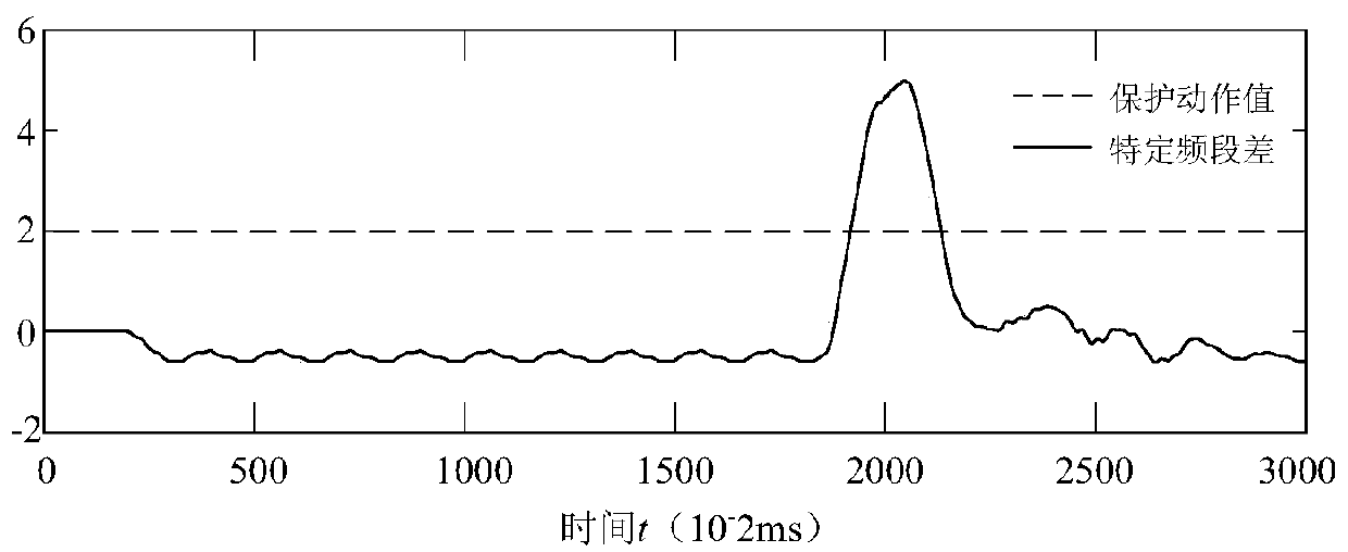
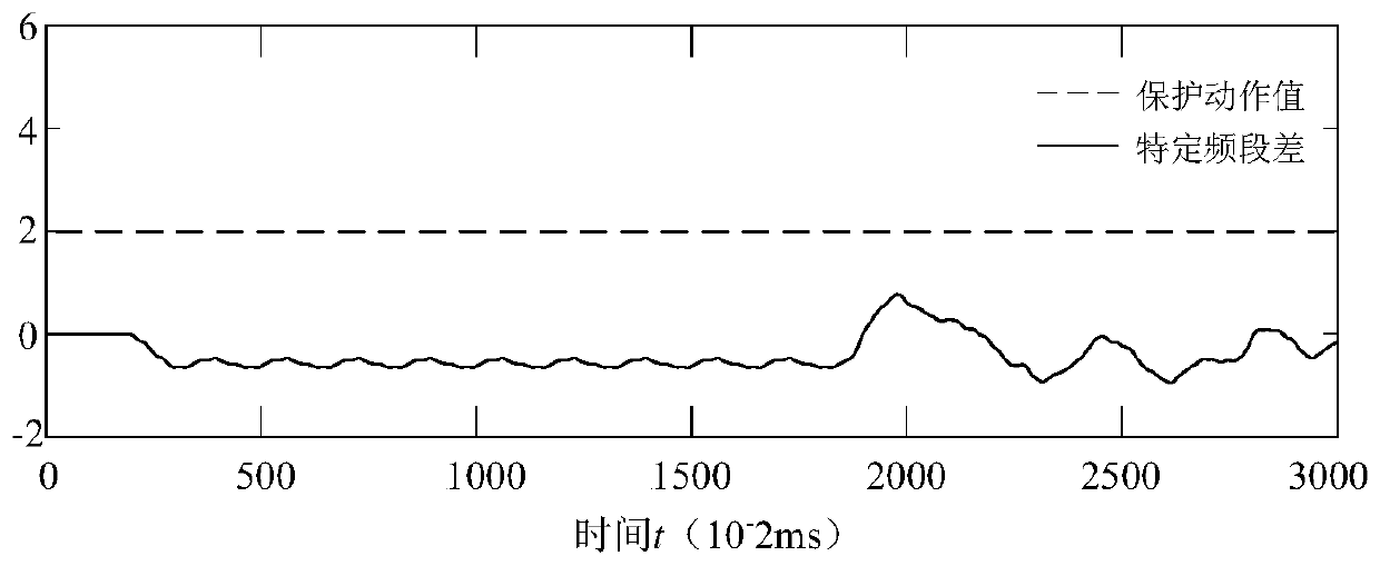
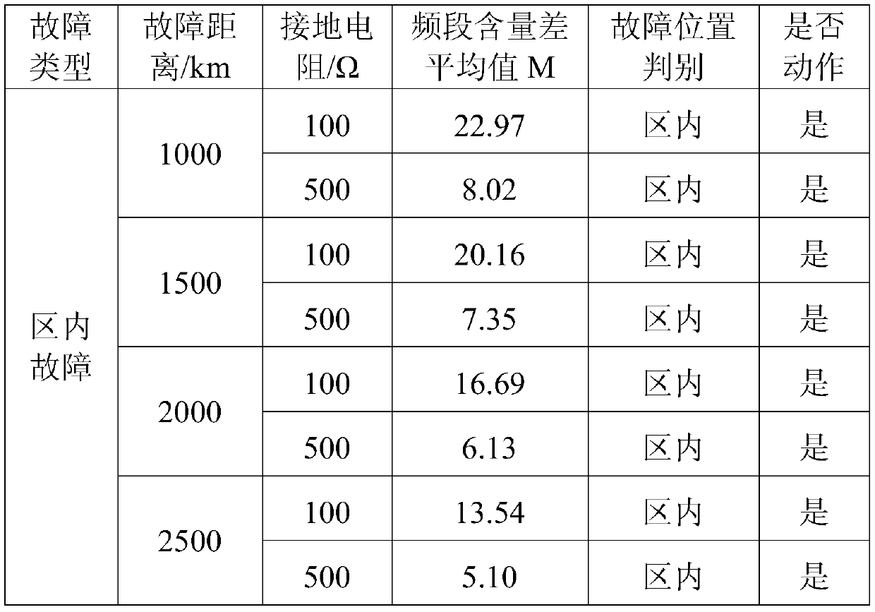

Image

  • A single-ended quick-acting main protection method for HVDC transmission lines
  • A single-ended quick-acting main protection method for HVDC transmission lines
  • A single-ended quick-acting main protection method for HVDC transmission lines

Examples


Embodiment

[0044] A specific embodiment of the present invention is a single-ended quick-acting main protection method for a high-voltage direct current transmission line, the steps of which are as follows:

[0045] A. Data collection

[0046] The protection device of the HVDC power transmission system collects the current at the outlet side of the rectifier of the DC transmission line and the current at the outlet side of the DC filter in real time at a sampling frequency of 100 kHz, and obtains the discrete value i of the rectified current at the current moment t respectively a (t) and the filtered current discrete value i at the current moment t b (t);

[0047] B. Processing of rectified current signal

[0048] The rectified current discrete value i of the previous 299 moments and the current moment t a (t-299), i a (t-298), i a (t-297)…i a (t-2), i a (t-1), i a (t), constituting the rectified current sequence I at the current moment t a (t),I a (t)=[i a (t-299), i a (t-29...


PUM


Abstract

A single-ended quick-acting main protection method for a high-voltage direct current transmission line, the steps of which are mainly: A. Collecting the outlet side current i of the rectifier a (t) and DC filter outlet side current i b (t); B. Perform wavelet decomposition and reconstruction of the rectified current at the last 300 moments to obtain the sum of the sub-high frequency rectified wavelet decomposition current; C. Perform wavelet decomposition and reconstruction of the filter current value at the latest 300 moments to obtain the second highest The wavelet decomposition current sum after frequency band filtering; D, calculate the difference D(t) between the wavelet decomposition current summation and the rectified wavelet decomposition current summation after the sub-high frequency band filtering; obtain the sub-high frequency band current difference average E of the last 100 moments, such as The average value of the current signal difference in the sub-high frequency band is greater than the set value D set , the main protection of the line will act; otherwise, it will not act. The main protection action of this method is more reliable and accurate.

Description

technical field [0001] The invention relates to a single-end quick-acting main protection method for a high-voltage direct current transmission line. Background technique [0002] The reverse distribution characteristics of my country's primary energy and power load determine that high-voltage transmission will occupy an increasingly important position in my country's power grid structure. In high-voltage transmission, compared with high-voltage AC transmission, high-voltage direct current transmission has constant voltage, no skin effect, greater transmission power, and better economic benefits, making it stand out in long-distance power transmission. At present, China Power Grid has built and put into operation 29 high-voltage DC transmission projects, including 7 ±800kV UHVDC transmission projects, forming a large-scale "West-to-East Power Transmission" and "North-to-South Power Transmission" energy allocation pattern. By 2020, the transregional and transnational power g...

Claims


Application Information

Patent Timeline
Patent Type & Authority Patents(China)
IPC IPC(8): G01R31/08G01R19/25
CPCG01R19/2509G01R31/085
Inventor 林圣戴文睿张海强
Owner SOUTHWEST JIAOTONG UNIV
Learn More