Laser guiding back charging method and chip for mobile robot

A mobile robot, laser-guided technology, applied in instruments, motor vehicles, non-electric variable control, etc., can solve the problems of difficult to define the angle of infrared modulated light, small laser-guided signal divergence, low docking success rate, etc.

Active Publication Date: 2019-03-22
AMICRO SEMICON CORP
View PDF5 Cites 21 Cited by
  • Summary
  • Abstract
  • Description
  • Claims
  • Application Information

AI Technical Summary

Problems solved by technology

Among them, modulated infrared guidance occupies a dominant position in the field of recharge technology due to its low cost and high precision, but it also has some disadvantages, such as: it is difficult to limit the angle of infrared modulated light, and the optical path needs to be limited by designing molds, so the optical path The accuracy depends on the specification design of the mould; at present, home smart robots can automatically return to the home for charging, and most of the mobile robots use a random pattern to find the infrared beam signal directly in front of the charger. Due to the poor linearity of the infrared light, the docking success rate Low, so it needs to be improved; in addition, during the laser guidance process, due to the small divergence of the laser guidance signal, it is easy to generate pseudoposon signals for mirror reflection imaging

Method used


Image

  • Laser guiding back charging method and chip for mobile robot
  • Laser guiding back charging method and chip for mobile robot
  • Laser guiding back charging method and chip for mobile robot

Examples


Embodiment Construction

[0023] In order to illustrate the present invention more clearly, specific examples are given below for further illustration.

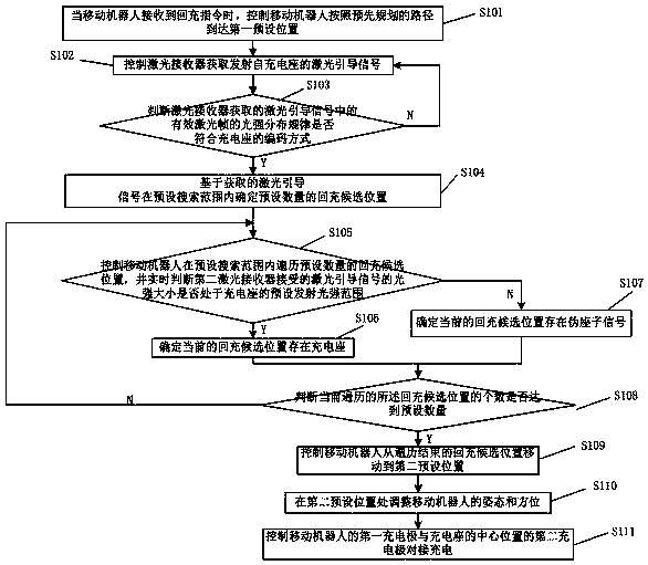
[0024] An embodiment of the present invention provides a laser-guided recharging method for a mobile robot. The laser recharging method is implemented on a mobile robot with a laser receiver and a charging stand with a laser transmitter.

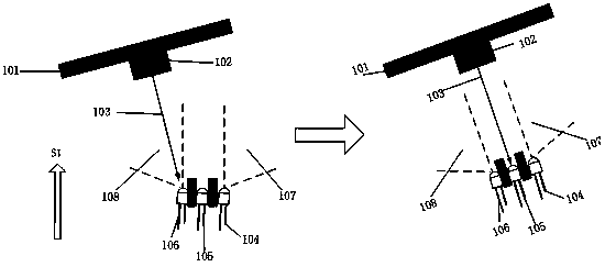
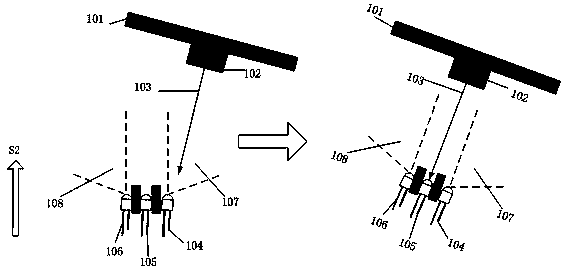
[0025] Refer below Figure 2 to Figure 3 The projection in the horizontal direction of the implementation object of the embodiment of the present invention is described.

[0026] Such as Figure 2 to Figure 3 As shown, the laser receiver includes a first laser receiver 104, a second laser receiver 105 and a third laser receiver 106, and the second laser receiver 105 is installed at the center position of the first charging pole of the mobile robot , the first laser receiver 104 and the third laser receiver 106 are respectively arranged side by side on both sides of the center position of the first charging pole. I...


PUM


Abstract

The invention discloses a laser guiding back charging method and chip for a mobile robot. The laser guiding back charging method comprises the steps of step 1, controlling the mobile robot to move toa first preset position; step 2, judging that whether an intensity distribution law of an effective laser frame acquired by a laser receiver conforms to an encoding mode of a charging cradle, and thenproceeding to step 3; step 3, determining a preset number of back charging candidate positions within a preset search range based on an acquired laser guiding signal; step 4, controlling the mobile to traverse a preset number of the back charging candidate positions within the preset search range; step 5, controlling the mobile robot to move to a second preset position; step 6, adjusting the posture and orientation of the mobile robot at the second preset position, and controlling a first charging pole of the mobile robot and a second charging pole of the central position of the charging cradle to be docked and charged, thereby improving the guiding precision and efficiency of the laser back charging.

Description

technical field [0001] The invention relates to the field of robot recharging control, in particular to a laser-guided recharging method and chip for a mobile robot. Background technique [0002] A more common approach is to guide the robot to a place where the charging stand can be identified through map navigation, and then use signals to guide the robot to get on the seat. For plane waves, the light intensity is constant, and the laser is close to plane waves. [0003] There are several common ways of signal guidance: adjusting infrared guidance, laser guidance, visual recognition guidance, ultrasonic guidance and so on. Among them, modulated infrared guidance occupies a dominant position in the field of recharge technology due to its low cost and high precision, but it also has some disadvantages, such as: it is difficult to limit the angle of infrared modulated light, and the optical path needs to be limited by designing molds, so the optical path The accuracy depends...

Claims


Application Information

Patent Timeline
Patent Type & Authority Applications(China)
IPC IPC(8): G05D1/02
CPCG05D1/0212G05D1/024G05D1/0274G05D2201/0217
Inventor 赖钦伟周和文肖刚军
Owner AMICRO SEMICON CORP
Why Eureka
Try Eureka