Converting station fire disaster early warning inspecting robot
A inspection robot and fire early warning technology, which is applied to fire alarms with electrical effects, fire alarms, and fire alarms that rely on radiation effects, etc., can solve problems such as poor adaptability, poor passing ability, and inability to patrol
- Summary
- Abstract
- Description
- Claims
- Application Information
AI Technical Summary
Problems solved by technology
Method used
Image
Examples
Embodiment 1
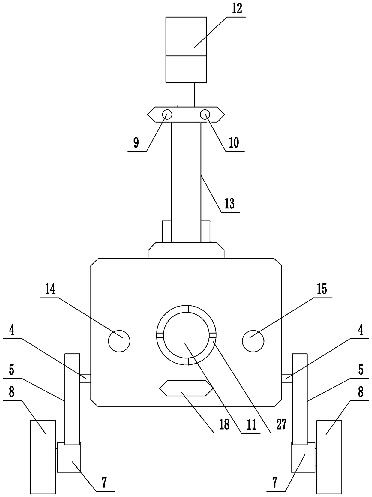
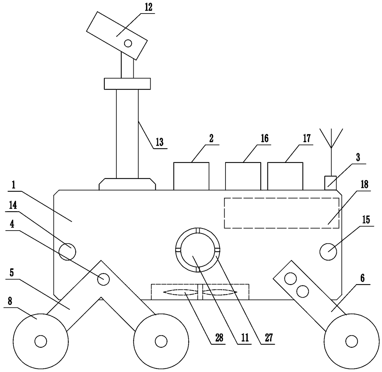
[0037] Such as figure 1 and figure 2 As shown, the present invention includes a robot body 1 and a walking device, a monitoring device, a control device 2 , a communication device 3 and a navigation and positioning device arranged on the robot body 1 .
[0038] The walking device comprises a front drive assembly and a rear drive assembly positioned at the lower end of the robot body 1, and the front drive assembly includes two V-shaped crank arms 5 ( figure 1 One is shown), the rear drive assembly includes two obliquely arranged brackets 6 ( figure 1 One is shown), the ends of the two V-shaped crank arms 5 and the two brackets 6 are provided with driving motors 7 , and the output shafts of the driving motors 7 are connected with rollers 8 through transmission.
[0039] Monitoring device comprises pyro-release infrared sensing module 9, ultraviolet sensing module 10, smoke sensing module 11, video acquisition module 12, pyro-release infrared sensing module 9, ultraviolet sen...
Embodiment 2
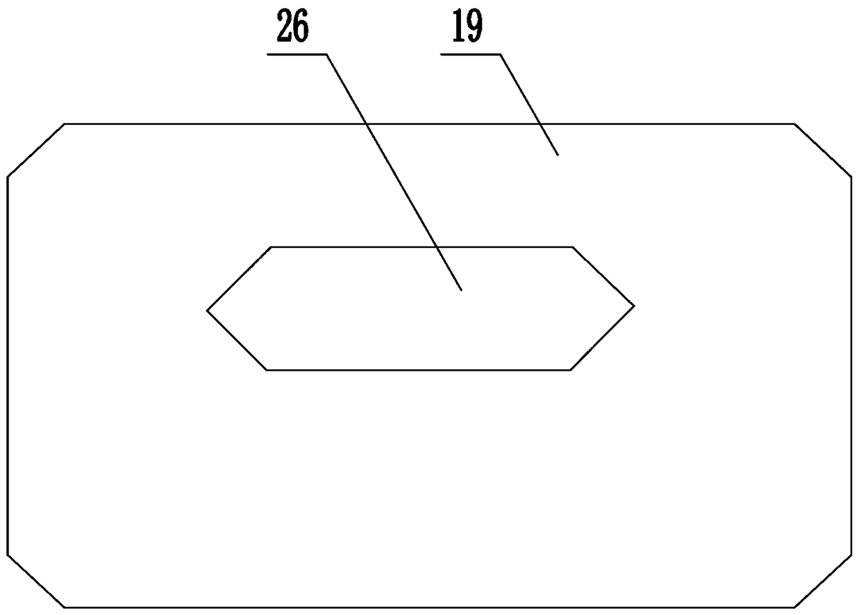
[0045] The structure of this embodiment is basically the same as that of Embodiment 1, the difference is: as image 3 As shown, the present invention also includes a charging pile 19. A charging interface 26 is arranged on the charging pile 19. A charging connector matching the charging interface is arranged on the outside of the robot body. The charging connector is connected to a rechargeable power source through a cable.
Embodiment 3
[0047] The structure of this embodiment is basically the same as that of Embodiment 1, the difference is: as Figure 4 and Figure 5 As shown, the video acquisition device includes a left visible light lens 20, a right visible light lens 21, an infrared light lens 22, and an ultraviolet light lens 23, and an image acquisition module 24 is arranged behind the left visible light lens 20 and the right visible light lens 21. The output end of the acquisition module 24 is connected to the input end of the control device 2 , the pyro-infrared sensing module 9 is located at the rear side of the infrared lens 22 , and the ultraviolet sensing module 10 is located at the rear side of the ultraviolet lens 23 .
PUM
 Abstract
Description
Claims
Application Information
 - R&D
- Intellectual Property
- Life Sciences
- Materials
- Tech Scout
- Unparalleled Data Quality
- Higher Quality Content
- 60% Fewer Hallucinations
Browse by: Latest US Patents, China's latest patents, Technical Efficacy Thesaurus, Application Domain, Technology Topic, Popular Technical Reports.
© 2025 PatSnap. All rights reserved.Legal|Privacy policy|Modern Slavery Act Transparency Statement|Sitemap|About US| Contact US: help@patsnap.com


