Busway

A technology for bus ducts and clamping components, applied in the field of bus ducts, can solve problems such as poor heat dissipation effect, and achieve the effects of reducing the incidence of accidents, improving safety and stability, and reducing siltation

Active Publication Date: 2019-03-22
ZHENJIANG YITUO ELECTRIC
View PDF8 Cites 9 Cited by
  • Summary
  • Abstract
  • Description
  • Claims
  • Application Information

AI Technical Summary

Problems solved by technology

[0004] The purpose of the present invention is to provide a busway to alleviate the technical problem of poor heat dissipation effect of the existing busway

Method used


Image

  • Busway
  • Busway
  • Busway

Examples


Embodiment 1

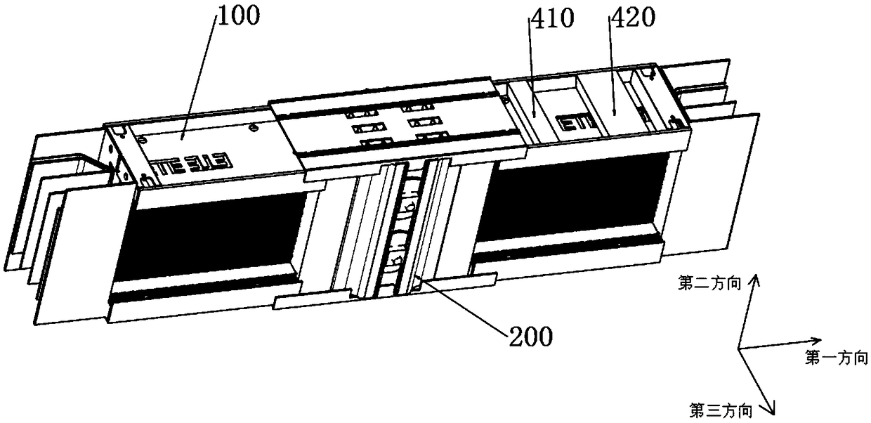
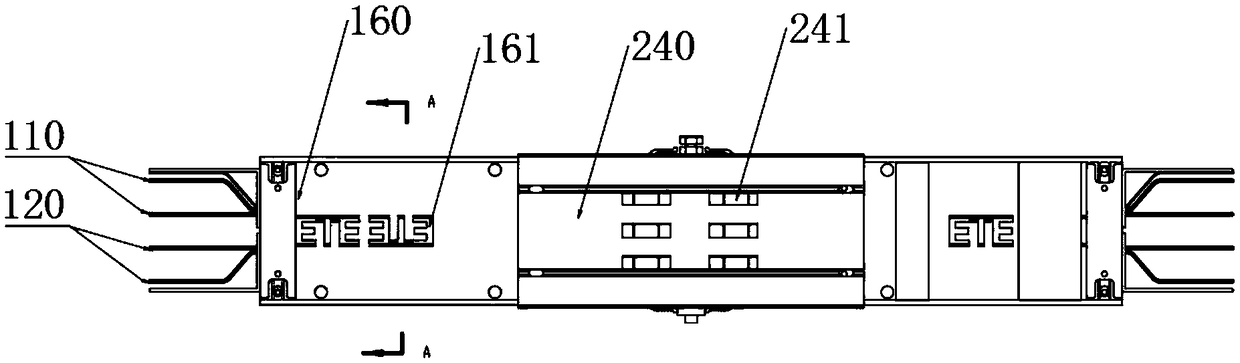
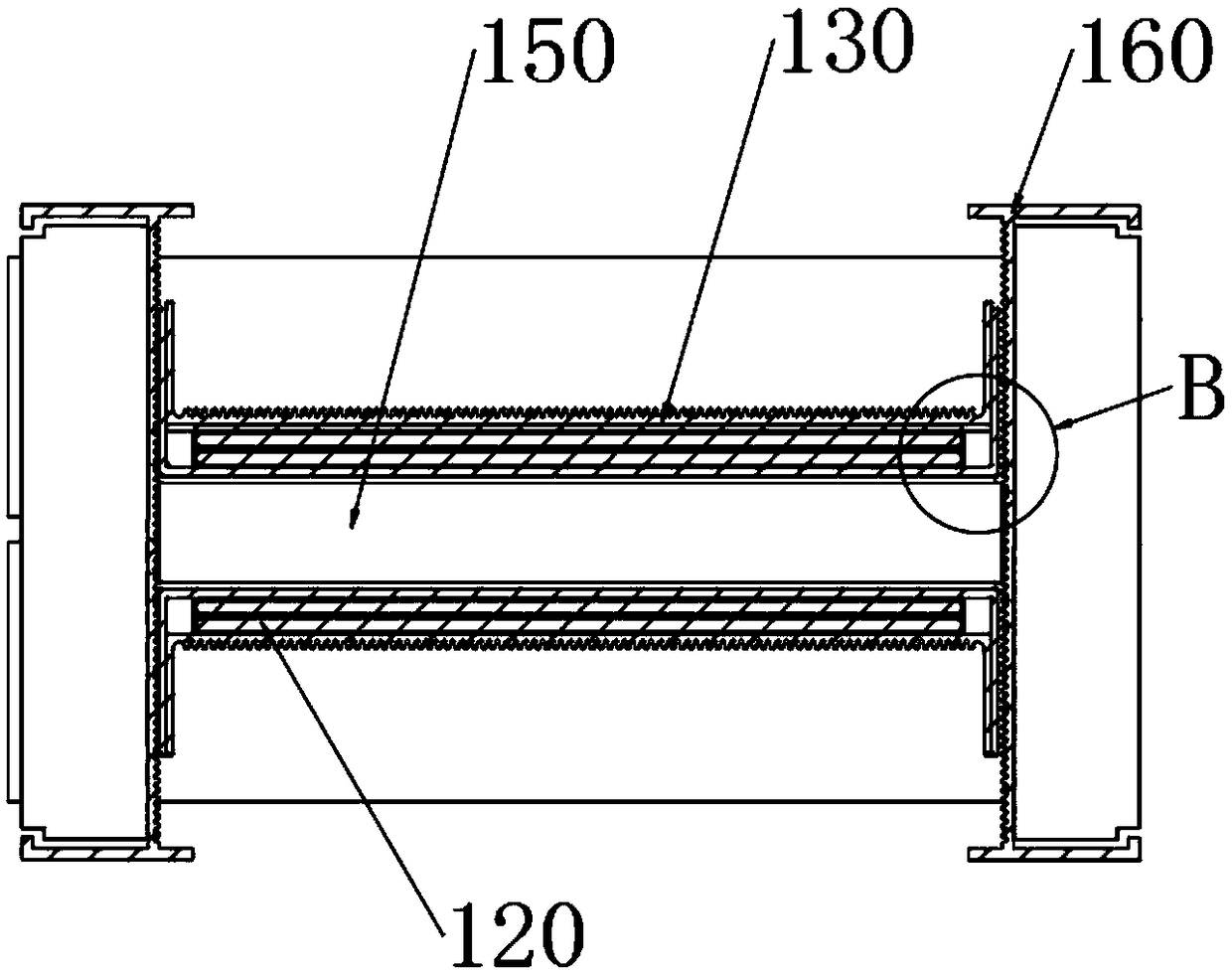
[0048] Such as Figure 1-Figure 3 As shown, the busway provided by the embodiment of the present invention includes: a busway unit 100, the busway unit 100 includes a housing, and a first conductor group 110 and a second conductor group 120 extending along a first direction, and the housing includes two Clamping assembly 130, the two clamping assemblies 130 respectively clamp and fix the first conductor set 110 and the second conductor set 120; the housing includes two spacers 140, the spacer 140 is located between the two clamping assemblies 130, Two spacers 140 are distributed at one end and the other end of the clamp assembly 130 at intervals, so that the two clamp assemblies 130 and the two spacers 140 enclose a heat dissipation channel 150 extending along the second direction; Two cover plates 160 arranged in parallel and at intervals, that is, an upper cover plate and a lower cover plate, the cover plates 160 are respectively connected with the two clamping assemblies 13...

Embodiment 2

[0073] Such as Figure 11-Figure 12 As shown, the difference from Embodiment 1 is that the number of heat dissipation through holes 231 on each heat dissipation part of the heat dissipation element 230 is one, and the edge of the second heat dissipation hole 241 of the connecting cover 240 extends toward the bottom surface. The barrel 242 and the inserting barrel 242 are used for inserting into the heat dissipation through hole 231 , and the outer wall of the inserting barrel 242 is in close contact with the inner wall of the heat dissipation through hole 231 .

[0074] Such as Figure 13 As shown, during installation, the heat dissipation through hole 231 of the heat sink 230 can be inserted on the socket 242 of the lower connection cover 240 first, and then the upper connection cover 240 is installed, and the insertion socket 242 on the upper connection cover 240 is plugged into the heat sink. At the other port of the through hole 231, external dust or water flows into the ...


PUM


Abstract

The present invention provides a busway and belongs to the field of power transmission equipment. The busway comprises busway units. The busway unit includes a housing, a first conductor group and a second conductor group which extend along a first direction; the housing comprises two clamping assemblies; the two clamping assemblies are respectively used for clamping and fixing the first conductorgroup and the second conductor group; the housing further comprises two partitioning components; the partitioning components are located between the two clamping assemblies; the two partitioning components are arranged at intervals on one end of the clamping assemblies and the other end of the clamping assemblies respectively, such that the two clamping assemblies and the two partitioning components enclose a heat dissipating passage extending along a second direction; the housing also comprises two cover plates which are arranged parallelly and spaced apart along the second direction; the cover plates are respectively connected to the two clamping assemblies; and first heat dissipation holes aligned with the heat dissipation passage are formed in the cover plates. The busway also comprises a temperature and humidity control system that automatically detects temperature and humidity inside the busway and adjusts the temperature and humidity through a fan, so as to improve heat dissipation and safety.

Description

technical field [0001] The invention relates to the field of power transmission equipment, in particular to a busway. Background technique [0002] With the emergence of modern engineering facilities and equipment, the power consumption of all walks of life is increasing rapidly, especially the emergence of many large workshops and high-rise buildings. The traditional cables used as power transmission wires can no longer meet the requirements of large current transmission systems. The parallel use of road cables brings a lot of inconvenience to the on-site installation and construction connection, and the emergence of busway solves this problem. The busway is a closed metal device composed of copper and aluminum busbars, which is used to distribute large power to various components of the decentralized system. [0003] The air-type busway is a kind of busway. The air-type busway supports the busbar in the shell with an insulating gasket. A large amount of heat is generated ...

Claims


Application Information

Patent Timeline
Patent Type & Authority Applications(China)
IPC IPC(8): H02G5/06H02G5/10
Inventor 曹云峰姚勇闫乐陈飞
Owner ZHENJIANG YITUO ELECTRIC
Why Eureka
Try Eureka