AI technical title is built by PatSnap AI team. It summarizes the technical point description of the patent document.
An elevator control device, motor technology, applied in the direction of AC motor control, control system, electrical components, etc.
Active Publication Date: 2021-12-03
SHANGHAI MITSUBISHI ELEVATOR CO LTD
View PDF5 Cites 0 Cited by
Summary
Abstract
Description
Claims
Application Information
AI Technical Summary
This helps you quickly interpret patents by identifying the three key elements:
Problems solved by technology
Method used
Benefits of technology
Problems solved by technology
Therefore, it is not feasible to directly use the AC contactor in the above-mentioned elevator device
Method used
Image
Click on the blue label to locate the original text in one second.
Reading with bidirectional positioning of images and text.
Examples
Embodiment 1
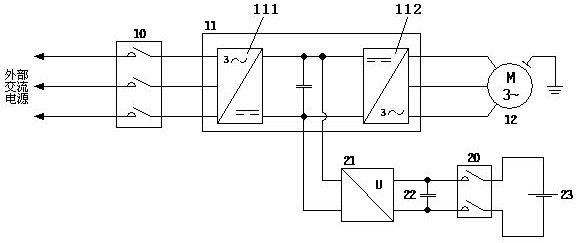
[0053] like figure 1 As shown, the elevator control device includes a second contactor 20 , a frequency converter 11 , a motor 12 , a DC converter 21 , a buffer capacitor 22 and an accumulator 23 .
[0054]The frequency converter 11 includes a rectifier 111 and an inverter 112, which are used to supply power to the motor 12 and drive the motor to run;
[0055] The input terminal of the rectifier 111 is connected to an external AC power supply, and the output DC voltage is sent to the input terminal of the inverter 112;
[0056] The inverter 112 inverts the DC voltage at its input terminal into an AC voltage to supply power to the motor 12;
[0057] The high voltage terminal of the DC converter 21 is connected to the input terminal of the inverter 112;
[0058] The second contactor 20 is connected between the low-voltage end of the DC converter 21 and the accumulator 23;
[0059] The buffer capacitor 22 is arranged between the DC converter 21 and the second contactor 20 , a...
Embodiment 2
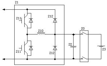
[0065] Based on the elevator control device of Embodiment 1, such as figure 2 As shown, the DC converter 21 includes two power switch tubes 211, two diodes 212 and a built-in inductor 210;
[0066] The power switch tube 211 includes a control terminal, a first terminal and a second terminal, and the conduction or cutoff between the first terminal and the second terminal is controlled by a voltage signal applied at the control terminal;
[0067] The first end of the first power switch tube 211 is connected to the positive input end of the inverter 112;
[0068] The second end of the first power switch tube 211 is connected to the first end of the second power switch tube 211;
[0069] The second terminal of the second power switch tube 211 is connected to the negative input terminal of the inverter 112;
[0070] The negative terminal of the first diode 212 is connected to the positive input terminal of the inverter 112;
[0071] The negative end of the second diode 212 is co...
PUM
Abstract
The invention discloses an elevator control device. The input terminal of the rectifier is connected with an external AC power supply, and the output DC voltage is sent to the input terminal of the inverter; the inverter converts the DC voltage at the input terminal into an AC voltage to supply power for the motor; The high-voltage end of the inverter is connected to the input end of the inverter; the second contactor is connected between the low-voltage end of the DC converter and the accumulator; the buffer capacitor is arranged between the DC converter and the second contactor, and the two ends of the buffer capacitor are respectively Connect the positive and negative ends of the low-voltage side of the DC converter. The elevator control device of the present invention has low cost.
Description
technical field [0001] The invention relates to elevator drive and control technology, in particular to an elevator control device. Background technique [0002] With the continuous deepening of the urbanization process, more and more buildings have begun to rise in the city, and the architectural space of the city is continuously extending in the vertical direction, which has also caused the use of elevators to rise steadily. Although the elevator provides great convenience for the vertical transportation of people in the building, it also consumes a lot of electric energy. [0003] When the elevator is running, the traction motor is in the state of regenerative power generation under the condition of heavy load downward, light load upward and deceleration. At this time, the elevator not only does not consume electric energy, but will convert part of the potential energy of the elevator system into electric energy and feed it back to the elevator system. middle. At presen...
Claims
Application Information
Patent Timeline
Application Date:The date an application was filed.
Publication Date:The date a patent or application was officially published.
First Publication Date:The earliest publication date of a patent with the same application number.
Issue Date:Publication date of the patent grant document.
PCT Entry Date:The Entry date of PCT National Phase.
Estimated Expiry Date:The statutory expiry date of a patent right according to the Patent Law, and it is the longest term of protection that the patent right can achieve without the termination of the patent right due to other reasons(Term extension factor has been taken into account ).
Invalid Date:Actual expiry date is based on effective date or publication date of legal transaction data of invalid patent.

