Anchor pile method static load test detecting device

Pending Publication Date: 2019-03-26
中汽建工(洛阳)检测有限公司
View PDF0 Cites 8 Cited by
  • Summary
  • Abstract
  • Description
  • Claims
  • Application Information

AI Technical Summary

Problems solved by technology

The following problems exist in the anchor plate welding process: 1. There are many anchor bars, resulting in longer welding time
The anchor plate welding is also used as a node item of the loading platform, which affects the development of subsequent pro

Method used


Image

  • Anchor pile method static load test detecting device
  • Anchor pile method static load test detecting device
  • Anchor pile method static load test detecting device

Examples


Embodiment 1

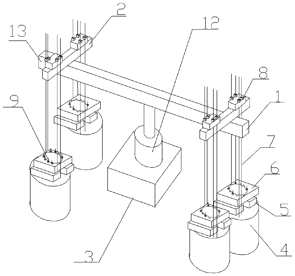
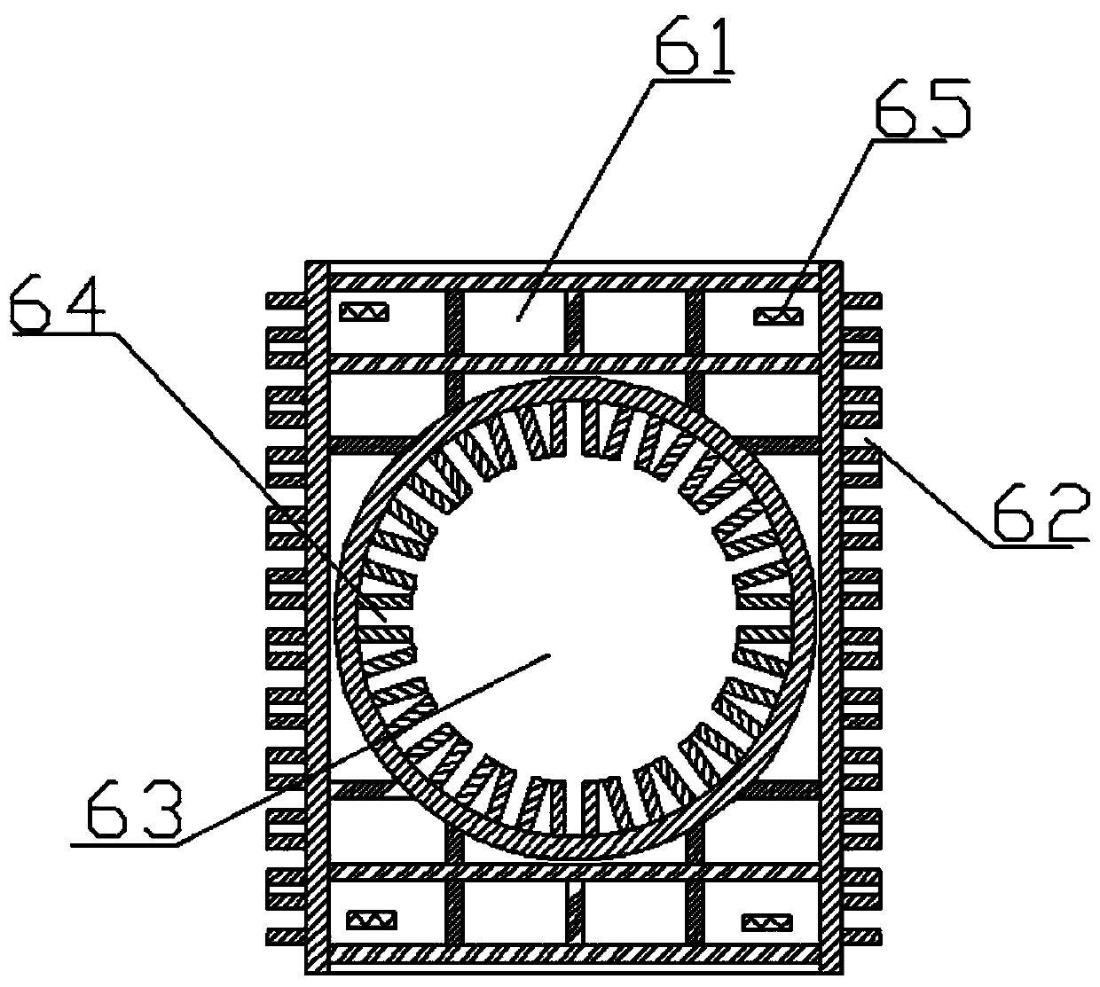
[0027] like figure 1 , 2 , shown in 4, 5, a kind of anchor pile method static load test detection device, comprises static load test pile 3, is located at the jack 12 above described static load test pile 3, and the top level of described jack 12 is provided with main girder 1. At least two secondary beams 2 perpendicular to the main beam 1 are arranged horizontally above the main beam 1, and the secondary beams 2 are symmetrically arranged on both sides of the jack 12, and each of the secondary beams Two anchor piles 4 are arranged directly below the anchor pile 2, and the anchor piles 4 are arranged symmetrically on both sides of the main beam 1; There is a row of parallel connecting rods 7, the connecting rods 7 are located on both sides of the secondary beam 2, and an anchor plate 6 is also arranged between the anchor pile 4 and the main beam 1, and the anchor plate 6 and the anchor A supporting member 5 is provided between the piles 4, and the anchor plate 6 includes a ...

Embodiment 2

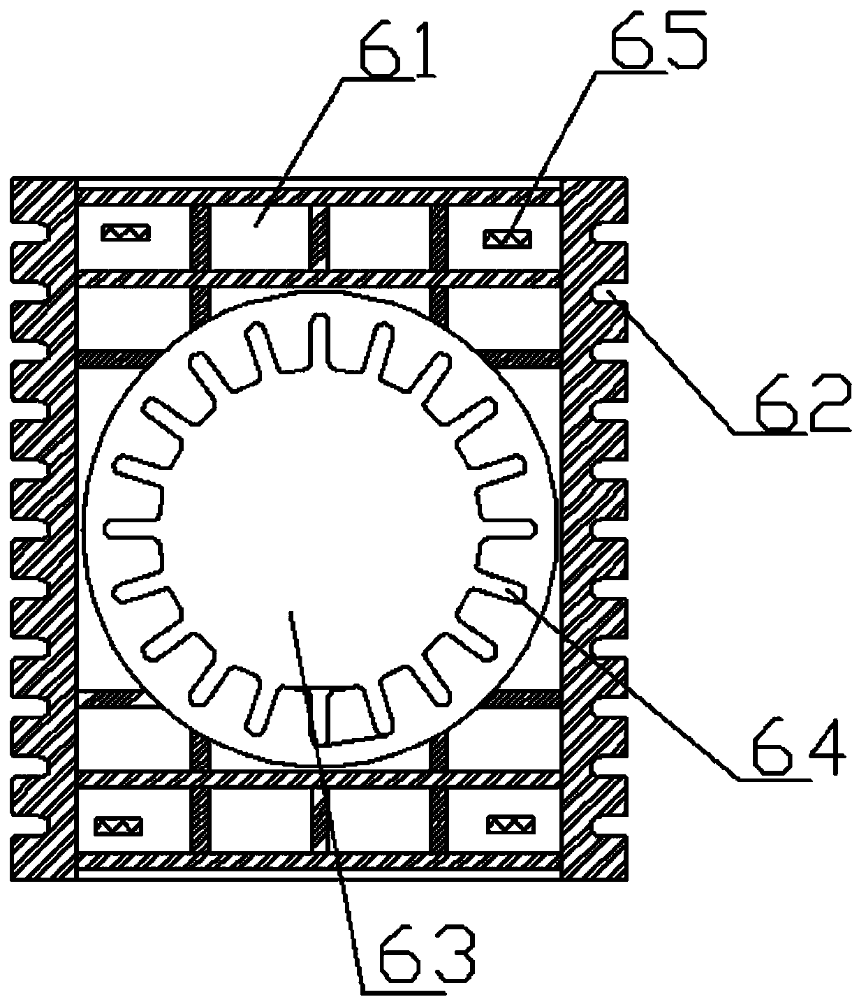
[0032] like figure 1 , 3 , shown in 4, 5, a kind of anchor pile method static load test detection device, comprises static load test pile 3, is located at the jack 12 above described static load test pile 3, and the top level of described jack 12 is provided with main girder 1. At least two secondary beams 2 perpendicular to the main beam 1 are arranged horizontally above the main beam 1, and the secondary beams 2 are symmetrically arranged on both sides of the jack 12, and each of the secondary beams Two anchor piles 4 are arranged directly below the anchor pile 2, and the anchor piles 4 are arranged symmetrically on both sides of the main beam 1; There is a row of parallel connecting rods 7, the connecting rods 7 are located on both sides of the secondary beam 2, and an anchor plate 6 is also arranged between the anchor pile 4 and the main beam 1, and the anchor plate 6 and the anchor The pile 4 is provided with a support member 5, and the anchor plate 6 includes a cuboid ...


PUM


Abstract

The invention discloses an anchor pile method static load test detecting device. A static load test pile and a jack arranged above the static load test pile are included. A main beam is horizontally arranged above the jack. At least two secondary beams perpendicular to the main beam are horizontally arranged above the main beam. Two anchor piles are arranged under each secondary beam, and the anchor piles are symmetrically arranged on the two sides of the main beam. A plurality of anchor ribs are arranged at the middle positions of the anchor piles, and each of the two sides is provided with arow of parallel connecting rods. The connecting rods are located on the two sides of the secondary beams. Anchor discs are further arranged between the anchor piles and the main beam, supporting pieces are arranged between the anchor discs and the anchor piles, and the upper ends of the anchor ribs are fixedly connected with the anchor discs. The upper ends of the connecting rods penetrate through the anchor boxes and are fixed to the positions above the secondary beams through steel bar fixing pieces. According to the anchor pile method static load test detecting device, design is reasonable, construction is convenient, the anchor ribs can be better positioned and fixed, and the construction period is effectively shortened.

Description

technical field [0001] The invention relates to the technical field of building construction, in particular to an anchor pile method static load test detection device. Background technique [0002] During the static load test of the foundation pile, the static load test is used for static load test and detection, and the small tonnage static load test is routinely completed by the surcharge method. The traditional method is to use the main beam and the secondary beam as the main components, and then use the anchor pile to provide the reaction force, and the four anchor piles are pre-embedded to quickly and simply connect the secondary beam to the street device, and then carry out the static load test on the test pile through the main beam , this linking method avoids a large number of conventional welding through the force transmission barrel, but the conventional static load test also needs to be welded, which is not only time-consuming, laborious, inefficient, but also inc...

Claims


Application Information

Patent Timeline
IPC IPC(8): E02D33/00E02D5/54
CPCE02D33/00E02D5/54
Inventor 杨晓斌姜兆平
Owner 中汽建工(洛阳)检测有限公司
Why Eureka
Try Eureka