High-protruding object periphery waterproof treatment device and method for steel structure roof

A technology of waterproof treatment and high protrusions, applied in the direction of roof, roof drainage, roof covering, etc., can solve problems such as roof leakage, masonry mortar and lock seal paste cracks, poor waterproof performance, etc., to avoid heat expansion and cold Shrinkage, water leakage hidden trouble solution, good waterproof effect

Inactive Publication Date: 2019-03-26
HUNAN JINHAI STEEL STRUCTURE
View PDF6 Cites 5 Cited by
  • Summary
  • Abstract
  • Description
  • Claims
  • Application Information

AI Technical Summary

Problems solved by technology

[0003] 1. The traditional waterproofing method usually adopts a herringbone-shaped shunt water retaining bar on the bottom roof of the high protrusion facing the slope of the roof to divert the water from the slope of the roof to avoid water leakage on the bottom roof of the high protrusion. However, in the heavy rain season, the rainwater will pass through The herringbone diverter water retaining strips form a huge water flow over the peaks of the roof tiles on both sides of the bottom of the high protrusion, and through the cracks at the connection position between the herringbone diverter water retaining strips and the roof panel locks, resulting in large-scale water leakage;
[0004] 2. When the traditional waterproof method is used for lateral waterproofing of high protrusions, sealing paste is used to seal the roof tiles on th

Method used


Image

  • High-protruding object periphery waterproof treatment device and method for steel structure roof
  • High-protruding object periphery waterproof treatment device and method for steel structure roof
  • High-protruding object periphery waterproof treatment device and method for steel structure roof

Examples


Embodiment Construction

[0026] The specific implementation of the invention will be further described below in conjunction with the accompanying drawings.

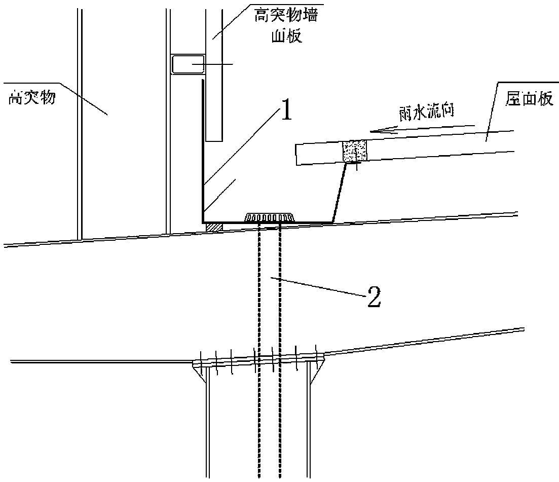
[0027] Such as figure 1 As shown, the waterproof treatment device around the high protrusions of the steel structure roof of the present invention includes a waterproof structure.

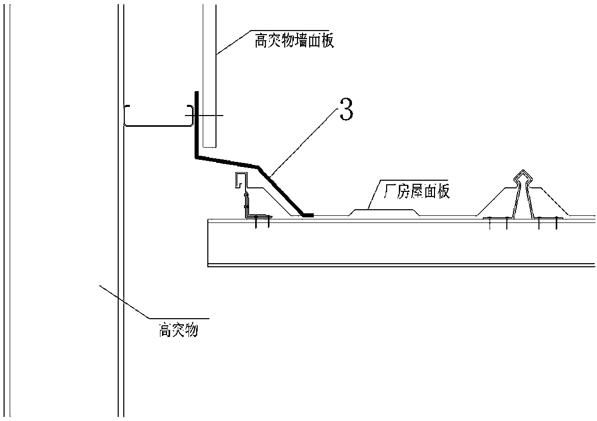
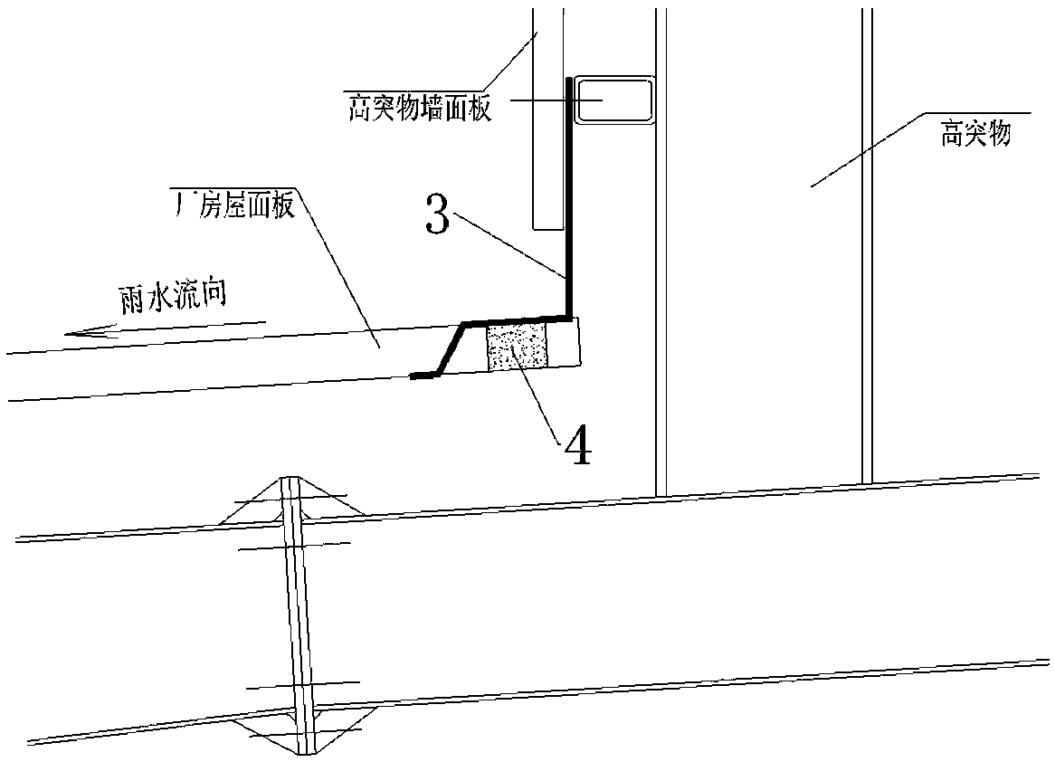
[0028] Such as Figure 1-3 As shown, the waterproof structure includes a gutter 1, a downpipe 2, a waterproof edge 3 and a waterproof plug 4; the gutter 1 is an inner wall type gutter, and the gutter 1 is installed between the roof protrusion and the roof panel. The gutter 1 is welded by white iron sheet. The cross section of the gutter 1 is U-shaped. The gutter 1 is arranged horizontally in the direction of the roof ridge of the house. The downpipe 2 is a plastic pipe fitting, the downpipe 2 runs through the lower end of the gutter 1, and the bottom end of the downpipe 2 communicates with the gutter on the ground of the house; the waterproof edge 3 is an L-shaped m...


PUM


Abstract

The invention discloses a high-protruding object periphery waterproof treatment device and method for a steel structure roof and belongs to the technical field of house water proofing. A waterproof structure comprises a gutter, a downpipe, waterproof closing edges and a waterproof plug. The gutter is an internal wall type gutter, is installed between a roof high-protruding object and a roof face plate and is made by welding a galvanized iron sheet, the cross section of the gutter is U-shaped, the gutter is transversely arranged in the side direction of a house ridge, flanges on the left and right sides of the gutter are respectively fixed to a roof high-protruding object wall face plate and the roof face plate, the gutter is utilized to collect rainwater from the house roof, the downpipe is utilized to drain water to the ground, it can be completely avoided that rainwater is accumulated to form huge water flow, the huge water flow is prevented from spilling over wave crests of the roofface plate to cause water leakage at lock catch positions of the roof face plate, meanwhile another three roof face plates at the bottom of the high-protruding object all adopt closing edges to serveas high-low-span flashing structures, a very good waterproof effect is played, and the applicability of the steel structure house is improved to some degree.

Description

technical field [0001] The invention relates to the technical field of house waterproofing, in particular to a device and method for waterproofing the periphery of high protrusions on a steel structure roof. Background technique [0002] When traditional waterproofing methods and devices are applied to the surrounding structures of steel structure roof overhangs, there are the following deficiencies: [0003] 1. The traditional waterproofing method usually adopts a herringbone-shaped shunt water retaining bar on the bottom roof of the high protrusion facing the slope of the roof to divert the water from the slope of the roof to avoid water leakage on the bottom roof of the high protrusion. However, in the heavy rain season, the rainwater will pass through The herringbone diverter water retaining strips form a huge water flow over the peaks of the roof tiles on both sides of the bottom of the high protrusion, and through the cracks at the connection position between the herri...

Claims


Application Information

Patent Timeline
IPC IPC(8): E04D13/064E04D13/072E04D13/08E04D13/16
CPCE04D13/064E04D13/0641E04D13/072E04D13/08E04D13/1687
Inventor 曾勇陈波
Owner HUNAN JINHAI STEEL STRUCTURE
Why Eureka
Try Eureka