
Four ram coiled tubing sealer

A technology of sealing device and four rams, which is applied in sealing/isolation, wellbore/well components, earthwork drilling and production, etc., can solve the problem that half-sealing cannot fully restore the sealing performance, increase the volume of wellhead devices, and have a great impact and other problems, to achieve the effect of reducing personal trauma accidents, reducing weight, and convenient operation and use

Active Publication Date: 2021-06-04
DAQING DANFENG PETROLEUM TECH DEV CO LTD
View PDF24 Cites 0 Cited by
  • Summary
  • Abstract
  • Description
  • Claims
  • Application Information

AI Technical Summary

Problems solved by technology

[0003] Among them, the full seal plays the role of safety guarantee when the well is shut down after shearing, and realizes no pipe sealing at the wellhead. However, in the 4FZ blowout preventer, due to the existing full seal sealing method, a combination of hydraulic and manual is adopted. Because of the mechanical method, it is often used as an alternative when the hydraulic control method is out of control, so it is not commonly used. However, the commonly used hydraulic method often occurs due to the long shutdown time of some wells due to seasonal or Blowout accidents caused by drastic changes in the weather will not only cause serious pollution to the environment, but also cause great harm to people sometimes
[0004] In addition, the semi-seal in the prior art is also called pipe seal. The semi-seal of the original 4FZ blowout preventer is also controlled by hydraulic pressure. The disadvantages of this horizontal double hydraulic cylinder sealing method are: The two half-sealed rams are butted, so their sealing performance is greatly affected by the hydraulic pressure and shape. Therefore, during operation, there are often cases where the half-sealed gate cannot fully restore the sealing performance due to the wear and tear of the sealing part and re-pressurization.
This patent adopts an integral fully-sealed ram, but its driving method is to install a lower ram active chamber on the outside of the blowout preventer, which not only increases the volume of the wellhead device, but also adopts a hydraulic method when sealing the well. Push the lower ram into the elastic valve seat to achieve full sealing. In addition, this structural design is not suitable for the well sealing device for the four-ram blowout preventer dedicated to coiled tubing.

Method used


Image

  • Four ram coiled tubing sealer
  • Four ram coiled tubing sealer
  • Four ram coiled tubing sealer

Examples


Embodiment 1-5

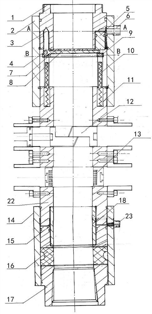
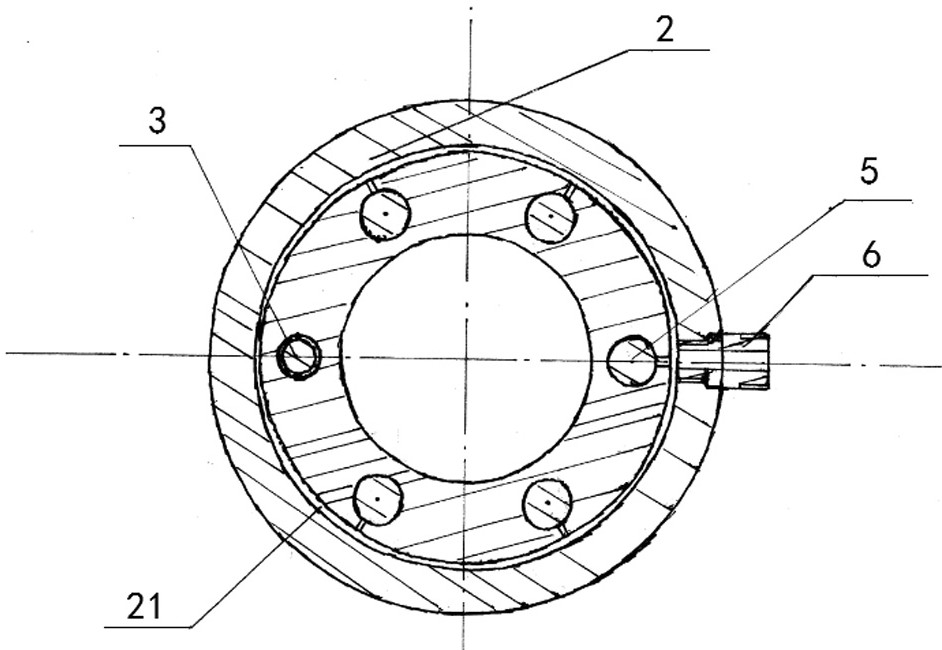
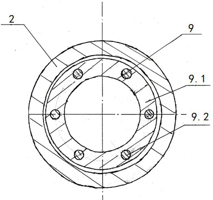
[0033] Embodiments 1-5, a coiled tubing well sealer with four rams mentioned in the present invention, its technical solution is: it includes a main housing 19 and a hydraulic cylinder 20, and the inner cavity of the main housing 19 is sequentially arranged from top to bottom Full-sealing device, shearing device, suspension device and semi-sealing device are installed, hydraulic cylinder 20 is installed on the outside of main housing 19, is used to drive full-sealing device, shearing device, suspension device or semi-sealing device action, described The fully sealed device includes upper joint 1, fully sealed outer cylinder liner 2, ram fixing bolt 3, ram shaft 4, ram opening piston group 5, connecting nozzle 6, sealing rubber 7, sealing carrier 8, ram closing bracket 9. The return spring 10 and the cutting and hanging body 11 are fixedly connected with the upper joint 1 and the cutting and hanging body 11 through the fully sealed outer cylinder liner 2, and there is a cavity f...

Embodiment 2

[0054] Embodiment 2, with reference to attached Image 6 , the difference between the present invention and Embodiment 1 is that a return force spring 10 is provided on the outside of the guide shaft 9.2, the lower end of the return force spring 10 is arranged on the upper end of the cutting and hanging body 11, and the upper end of the return force spring 10 is in contact with the lower surface of the connection plate 9.1 In this way, the guide shaft can also be moved up and down along the reserved cylindrical groove of the cutting and hanging body 11, and at the same time, the accumulated spring compression force can make the sealing ram be pressed to the lower end surface of the upper joint when the well is sealed; in addition , the guide shaft 9.2 provided here can adopt a solid structure, since it is not necessary to install a spring in the inner cavity of the guide shaft, it is not necessary to adopt a hollow structure.

Embodiment 3

[0055] Embodiment 3, with reference to attached Figure 7 , the difference between the present invention and embodiments 1 and 2 is: the sealing device used in the present invention adopts the full sealing device, shearing device and suspension device in embodiments 1 and 2, but what the half sealing device adopts is the existing The semi-enclosed device of technology, like this, the improvement of the present invention is just limited to full-enclosed device, specifically as follows:

[0056]The present invention comprises a main housing 19 and a hydraulic cylinder 20, and a full-sealing device, a shearing device, a suspension device and a half-sealing device are successively installed in the inner chamber of the main housing 19 from top to bottom, and a The hydraulic cylinder 20 is used to drive the action of the full-sealing device, the shearing device, the suspension device or the semi-sealing device. The full-sealing device includes an upper joint 1, a full-sealing outer ...


PUM


Abstract

The invention relates to a four-ram coiled tubing sealer. The technical solution is: including the main shell and the hydraulic cylinder, install the full sealing device, the shearing device, the suspension device and the semi-sealing device in the inner cavity of the main shell from top to bottom. When sealing the well, close the bracket through the gate The seal carrier is supported on the lower end surface of the upper joint by the return spring and the return spring to realize the seal; during the workover, the piston group is driven down by hydraulically driving the ram, and the seal carrier is pushed away, and further pressed down, so that the seal carrier rotates around the ram shaft , the coiled tubing can be run downhole along the inner cavity of the upper joint. The beneficial effect of the present invention is: because the whole seal is a vertical structure, that is, at least one double wing is removed, the working space is expanded, and the personal trauma accidents in the working are greatly reduced; the weight of the whole device is also greatly reduced, In this way, the difficulty in the operation reduces the processing cost, and it is safer and more reliable than the original 4FZ blowout preventer, more convenient to use, lower in processing cost and lighter in weight.

Description

technical field [0001] The invention relates to a coiled tubing sealing device and method, in particular to a coiled tubing sealing device with four rams. Background technique [0002] During the construction of coiled tubing in oil production, the 4FZ blowout preventer, that is, the four-ram blowout preventer, is a safety protection device that must be installed. In this device, the coiled tubing four-ram blowout preventer is Coiled tubing plays a pivotal role in the operation, and it is used to prevent blowout during the coiled tubing operation. Equipped with four ram assemblies, it can realize wellhead without pipe sealing, tubing shearing, tubing suspension, and pipe sealing; it is suitable for high-pressure wellhead and H2S working environment, adopts hydraulic drive, fast response speed, and manual locking, safety factor high. [0003] Among them, the full seal plays the role of safety guarantee when the well is shut down after shearing, and realizes no pipe sealing ...

Claims


Application Information

Patent Timeline
Patent Type & Authority Patents(China)
IPC IPC(8): E21B33/06
CPCE21B33/061
Inventor 陈超段希国王蕾王鑫曲林林曹婧婧任行杰唐会丽唐天丽李坤
Owner DAQING DANFENG PETROLEUM TECH DEV CO LTD
Learn More