

Delayed water inlet mechanism
A technology of water inlet mechanism and water inlet valve, which is applied to mechanical equipment, water supply devices, engine components, etc., to achieve the effect of high reliability and simple structure
- Summary
- Abstract
- Description
- Claims
- Application Information
AI Technical Summary
Problems solved by technology
Method used
Image

Examples
Embodiment 1
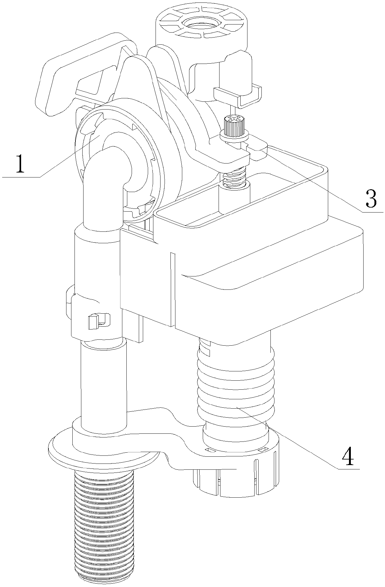
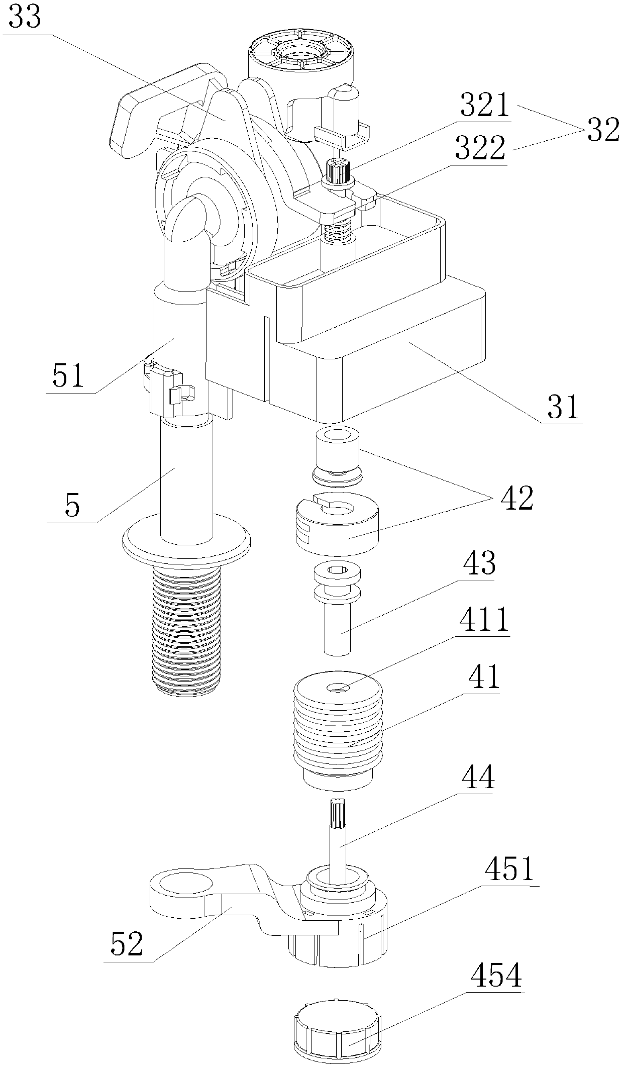
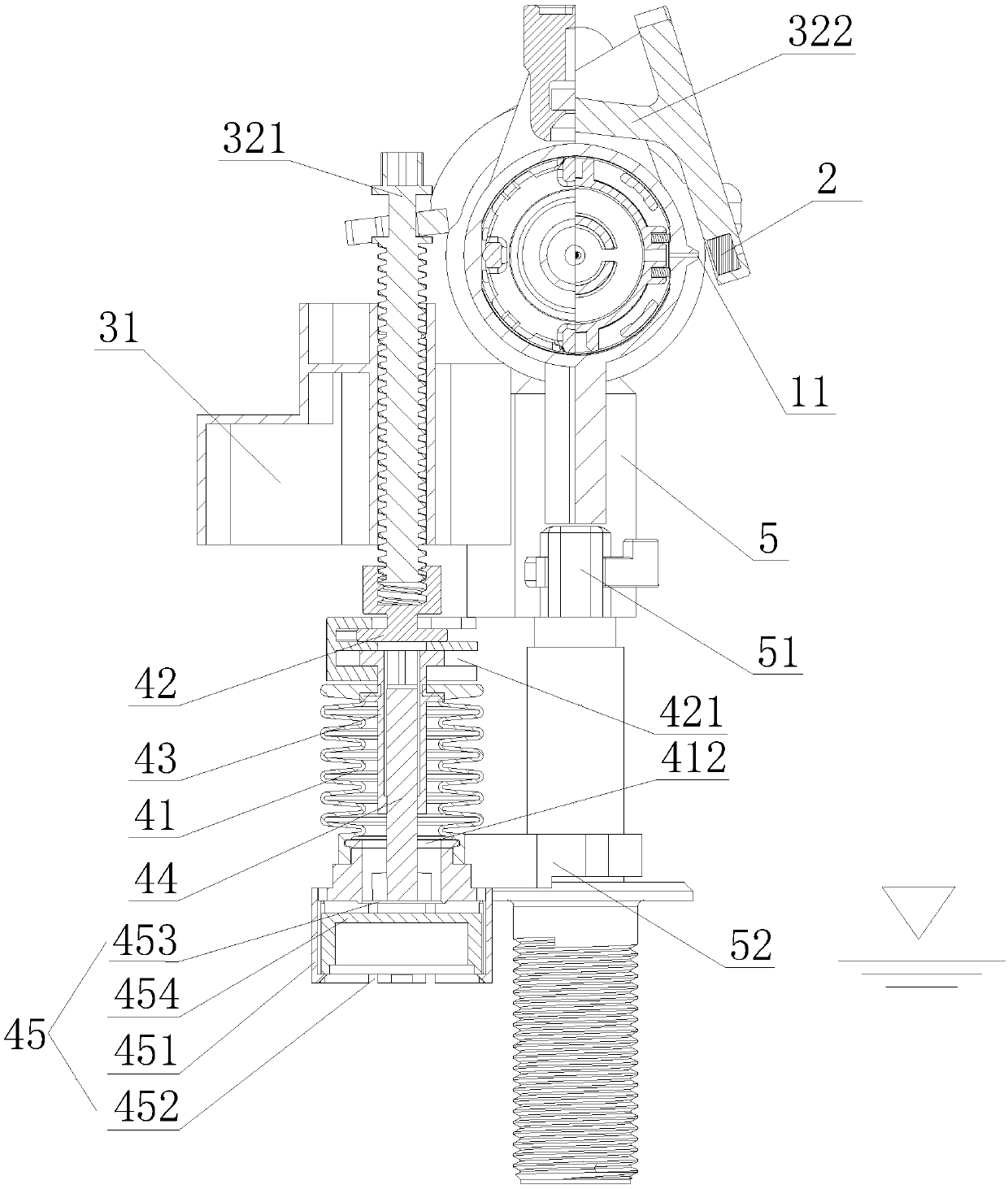
[0053] Such as Figure 1-9 As shown, the first embodiment of the present invention provides a delayed water inlet mechanism, including a water inlet valve and a delay assembly 4, the water inlet valve is a commonly used water inlet valve, including a valve part 1, a seal 2 and a water level control Component 3.
[0054] The water inlet valve is made of hard material. In this embodiment, the water inlet valve is used in the toilet tank. Therefore, it is preferably made of a corrosion-resistant plastic material.
[0055] The valve portion 1 includes a pressure relief port 11, and the seal 2 is used to seal the pressure relief port 11. The seal 2 may be a commonly used sealing device. In this embodiment, a rubber gasket is used. Those skilled in the art can choose other sealing materials.
[0056] The water level control assembly 3 drives the sealing element 2 to act, and the position where the sealing element 2 and the pressure relief port 11 are sealed and matched is the sealing posi...
Embodiment 2
[0081] Such as Figure 10-18 As shown, the second embodiment of the present invention provides a delayed water intake mechanism, which includes a water intake valve and a delay assembly 4, and the water intake valve includes a valve portion 1, a seal 2 and a water level control assembly 3.
[0082] The valve portion 1 includes a pressure relief port 11, and the seal 2 is used to seal the pressure relief port 11. The seal 2 may be a commonly used sealing device. In this embodiment, a rubber gasket is used.
[0083] The water level control assembly 3 drives the sealing element 2 to act, and the position where the sealing element 2 and the pressure relief port 11 are sealed and matched is the sealing position, and the sealing element 2 is separated from the pressure relief port 11 The position at is the pressure relief position, and the water level control assembly 3 includes a floating body 31 and a seal control mechanism 32 connected by the floating body 31.
[0084] In this embodimen...
Embodiment 3
[0101] Such as Figure 19-23 As shown, the third embodiment of the present invention provides a water inlet valve with a delayed water stop function. The structure provided in this embodiment is basically the same as that provided in the second embodiment. The difference is that in this embodiment, the delay The assembly 4 includes: the cavity of the delay assembly 4 is a third cylinder 48 provided with the first through hole 411, and the cavity adjustment assembly includes a cavity that is arranged inside the third cylinder 48 and The second piston 491, which can reciprocate along the axis, and the middle part are fixedly connected to the second piston 491. The two ends of the second piston rod 492 respectively penetrated from both ends of the third cylinder 48, the second The end of the piston rod 492 away from the first through hole 411 is connected to the rod 321 of the water level control assembly 3, and the second piston 491 and the third cylinder 48 form an inner end clo...
PUM
 Abstract
Description
Claims
Application Information