A utility boiler flue gas waste heat utilization system

A technology for flue gas waste heat and power plant boilers, applied in indirect heat exchangers, lighting and heating equipment, etc., can solve the problems affecting the efficiency of heat exchange and the decline of heat exchange capacity, and achieve smooth flow, suppression of backflow, and uniform distribution. Effect

Inactive Publication Date: 2019-09-13
山东电力高等专科学校
View PDF5 Cites 0 Cited by
  • Summary
  • Abstract
  • Description
  • Claims
  • Application Information

AI Technical Summary

Problems solved by technology

During the evaporation process of the heat pipe, it will inevitably carry liquid to the steam end. At the same time, because of the exothermic condensation of the condensation end, there will be liquid in the condensation end, and the liquid will inevitably mix with the steam, so that the fluid in the heat pipe is vapor. Liquid mixture, the existence of vapor-liquid mixture causes the gas to mix together, and the heat exchange capacity between the liquid and the liquid decreases, which greatly affects the heat exchange efficiency

Method used


Image

  • A utility boiler flue gas waste heat utilization system
  • A utility boiler flue gas waste heat utilization system
  • A utility boiler flue gas waste heat utilization system

Examples


Embodiment Construction

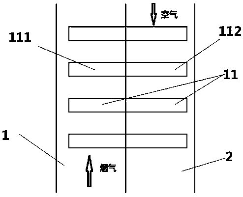
[0032] A boiler flue gas waste heat utilization system. The waste heat utilization system includes a heat pipe 11, a flue gas channel 1 and an air channel 2. The heat pipe 11 includes an evaporation end 111 and a condensation end 112, and the condensation end 112 is arranged in the air In the channel 12, the evaporation end 11 is arranged in the flue. The evaporation end 111 absorbs the waste heat of the flue gas in the boiler flue, and transfers the heat to the air in the air passage 12 through the condensation end 112. The preheated air enters the boiler furnace to support combustion.

[0033] During operation, the heat pipe of the present invention absorbs heat from the flue gas through the evaporating end 111, and then releases the heat to the air at the condensing end, the fluid is condensed, and then enters the evaporating end 111 by the action of gravity.

[0034] During the operation of the waste heat utilization device, there is uneven fluid distribution, and because the ...


PUM


Abstract

The invention provides a utility boiler flue gas waste heat utilization system, which includes a heat pipe, a flue gas channel and an air channel. The heat pipe includes an evaporation end and a condensation end, and the condensation end is arranged in the air channel; The residual heat of the flue gas transfers heat to the air in the air channel through the condensation end; the heated air enters the boiler furnace for combustion support, and a stabilizing device is installed in the heat pipe. The invention provides a flue gas waste heat utilization device and method with a novel structure, which fully utilizes heat sources, reduces energy consumption, and improves smoke exhaust effect.

Description

Technical field [0001] The present invention is part of a subject project jointly developed with an enterprise, and relates to the field of heat pipe waste heat recovery, and in particular to a method and device for recovering flue gas waste heat using heat pipes. Background technique [0002] With the rapid economic development of our country, energy consumption is increasing, and the problem of deteriorating urban air quality has become more and more prominent. The problems of saving energy and reducing the emission of environmental harmful substances are urgent. In the common steam generation process, one of the main reasons for high energy consumption and serious pollution is that the exhaust temperature of the boiler flue gas is too high, which wastes a lot of energy. Therefore, the waste heat of the boiler exhaust gas is recovered and reused to achieve energy saving and emission reduction. Purpose, while also protecting the environment. However, in the prior art, low-tempe...

Claims


Application Information

Patent Timeline
Patent Type & Authority Patents(China)
IPC IPC(8): F23J15/06F28D21/00
CPCF28D15/02
Inventor 刘红蕾张瀚艺李旭同张兵兵李振张行马委廉根宽胡全君马军江程李言伟
Owner 山东电力高等专科学校
Why Eureka
Try Eureka