Slide valve cleaning and drying machine for railway vehicle brake system

A braking system, railway vehicle technology, applied to dryers, cleaning methods using gas flow, drying, etc., can solve problems such as difficult to know, high labor intensity, difficult to pass environmental assessment, etc., to improve usability, cleaning Good effect and labor-saving effect

Pending Publication Date: 2019-03-26
成都智泰轨道技术有限公司
View PDF6 Cites 1 Cited by
  • Summary
  • Abstract
  • Description
  • Claims
  • Application Information

AI Technical Summary

Problems solved by technology

This kind of operation causes the cleaning fluid to fly everywhere with the high-pressure wind, and the workplace is everywhere, and it is difficult to know whether the inner cavity of the slide valve is dry.
At the same time, this method is inefficient, labor-intensive, and the drying effect is not clear, and it is easy to inhale the cleaning liquid into the lungs of the operator, affecting the health of the operator, and it is difficult to pass the environmental assessment. To solve this problem, a HFC slide valve dryer was developed.

Method used


Image

  • Slide valve cleaning and drying machine for railway vehicle brake system
  • Slide valve cleaning and drying machine for railway vehicle brake system
  • Slide valve cleaning and drying machine for railway vehicle brake system

Examples


Embodiment Construction

[0041] The application will be further described in detail below in conjunction with the accompanying drawings and embodiments. It should be understood that the specific embodiments described here are only used to explain related inventions, rather than to limit the invention. It should also be noted that, for ease of description, only parts related to the invention are shown in the drawings.

[0042] It should be noted that, in the case of no conflict, the embodiments in the present application and the features in the embodiments can be combined with each other. The present application will be described in detail below with reference to the accompanying drawings and embodiments.

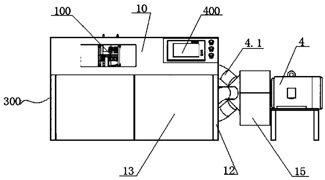
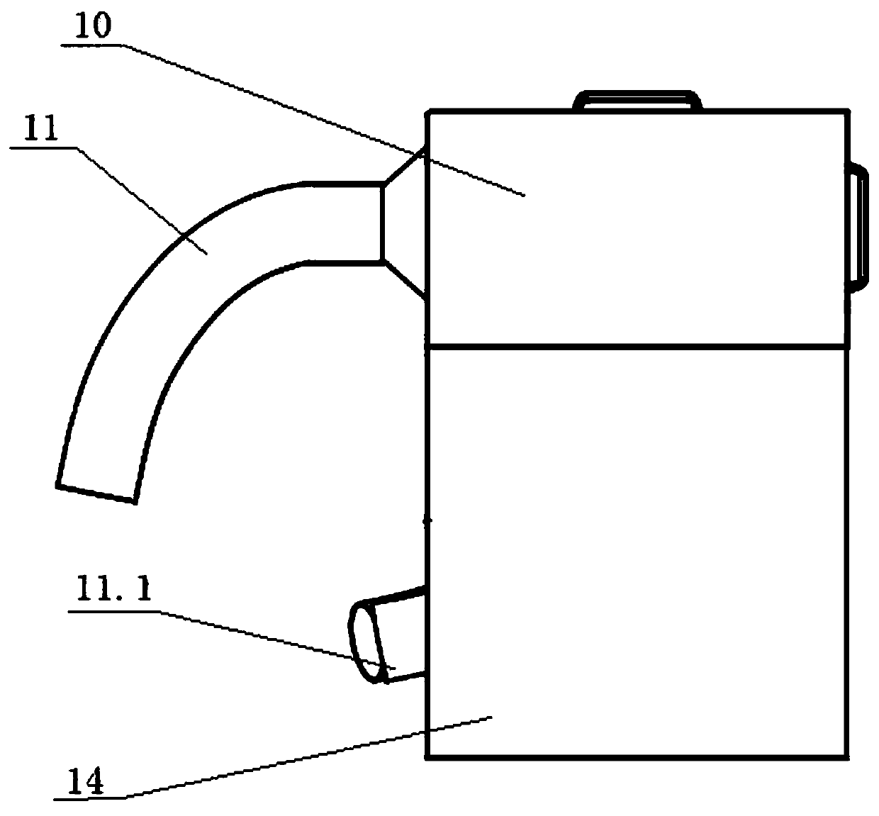
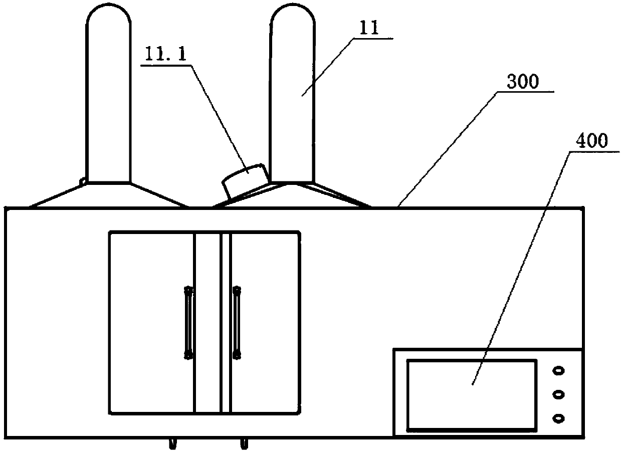
[0043] Please refer to figure 1 - Figure 10 , a sliding valve cleaning machine for a railway vehicle braking system, comprising a cleaning mechanism 100, a frame 200, a shield mechanism 300 and an electrical control 400, the cleaning mechanism 100 including a sliding valve tray 1, a moving mecha...


PUM


Abstract

The invention discloses a slide valve cleaning and drying machine for a railway vehicle brake system. The slide valve cleaning and drying machine comprises a cleaning and drying mechanism, a rack, a protective housing mechanism and an electric control system. The cleaning and drying mechanism comprises a slide valve tray, a moving mechanism, an air nozzle assembly and a ventilator. The protectivehousing mechanism comprises an upper cover, dust suction pipes A, a lower cover, cabinet doors and seal plates. The electric control system comprises multiple solenoid valve sets, a start and stop switch and a touch screen. Air nozzles of the air nozzle assembly are sequentially controlled by solenoid valves of the solenoid valve sets. By means of the slide valve cleaning and drying machine, residual liquid on the surfaces and in inner chambers of a slide valve (104) and a slide valve (120) can be effectively cleared away; the efficiency is high; thorough cleaning can be achieved; and the environment and operators are not polluted. The machine is of an all-enclosed structure; cleaning liquid is prevented from spattering, and it is guaranteed that the operators cannot inhale the cleaning liquid; and a working site is clean and meets the environment protection requirement of the state. Meanwhile, the 12 slide valves can be cleaned and dried one time; the cleaning time does not exceed oneminute; the speed is high; and the cleaning effect is good. Manual work can be saved, and usability of manual work is effectively improved.

Description

technical field [0001] The present disclosure generally relates to cleaning equipment, in particular to a sliding valve cleaning machine for a railway vehicle braking system. Background technique [0002] At present, the main valves used in the braking system of railway vehicles are 104 valves (passenger cars) and 120 valves (trucks). The key components of the 104 and 120 valves - slide valves, after ultrasonic cleaning, the surface and inner cavity remain Certain cleaning fluid must be cleaned up before storage. The current method used is that the operator holds the slide valve in one hand and the high-pressure air gun in the other hand, blows air on each channel first, and then blows air on the outer surface of the slide valve. After feeling dry, put it into a toolbox and store it. This kind of operation causes the cleaning fluid to fly everywhere with the high-pressure wind, and it is everywhere in the workplace, and it is difficult to know whether the inner cavity of th...

Claims


Application Information

Patent Timeline
Patent Type & Authority Applications(China)
IPC IPC(8): F26B21/00B08B5/04
CPCF26B21/00B08B5/043
Inventor 杜新民
Owner 成都智泰轨道技术有限公司
Why Eureka
Try Eureka