Arrival direction estimation algorithm based on rotation characteristic of signal subspace

A technology of direction of arrival estimation and signal subspace, applied in the field of signal processing, can solve problems such as poor estimation stability, and achieve the effects of reducing dimension, reducing computational complexity, improving low signal-to-noise ratio and fewer snapshots

Pending Publication Date: 2019-03-26
KUNMING UNIV OF SCI & TECH
View PDF7 Cites 5 Cited by
  • Summary
  • Abstract
  • Description
  • Claims
  • Application Information

AI Technical Summary

Problems solved by technology

[0004] The invention proposes a DOA estimation algorithm based on the rotation characteristics of the signal subspace, which mainly solves the problem of poor estimation stability of the ESPRIT algorithm under low signal-to-noise ratio and few snapsh

Method used


Image

  • Arrival direction estimation algorithm based on rotation characteristic of signal subspace
  • Arrival direction estimation algorithm based on rotation characteristic of signal subspace
  • Arrival direction estimation algorithm based on rotation characteristic of signal subspace

Examples


Embodiment 1

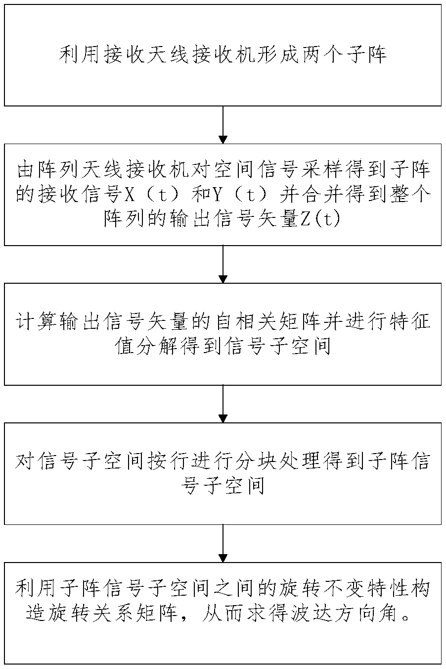
[0033] Embodiment 1: as figure 1 As shown, a DOA estimation algorithm based on the rotation characteristics of the signal subspace, the specific steps are as follows:

[0034] Step 1: Form two sub-arrays using the antenna receiver

[0035] Place a pair of antenna receivers at every distance d, each pair of receivers contains two array elements with exactly the same response characteristics, and the distance between the array elements is the known displacement vector Δ, a total of M are placed to form a uniform linear array, and the array is divided into are two sub-arrays X and Y with a translation vector of Δ, and the sub-arrays X and Y are respectively composed of x 1 ,x 2 ,...x M and y 1 ,y 2 ,...y M constitute. Assume that there are P far-field narrowband signals incident on the uniform linear array, and Gaussian white noise with zero mean value is added to the signal during propagation, where M≥P, λ is the wavelength of the incident signal.

[0036] Step 2: Samp...

Embodiment 2

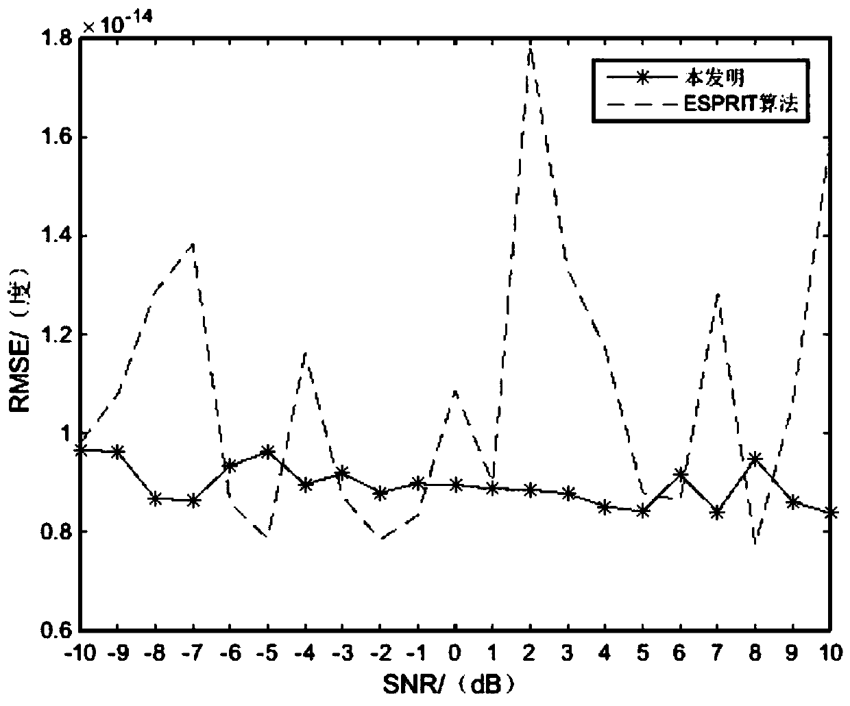
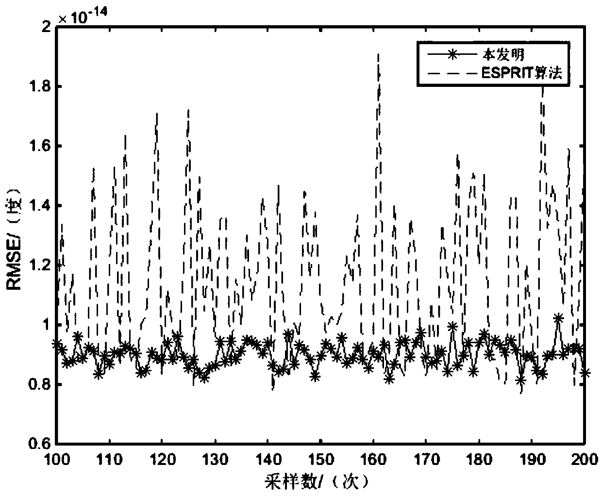
[0062] Embodiment 2: Calculate according to the method in Embodiment 1, wherein a uniform line array composed of 8 omnidirectional array elements is considered, the number of sub-array elements is 7, and the output of the first 7 array elements is expressed as sub-array 1 , the output of the last 7 array elements is represented as sub-array 2, the array element spacing is 0.5, and the search range of the spatial angle is [-90° 90°].

[0063] The formula for calculating the mean square error is:

[0064] In the formula, I represents the number of Monte Carlo experiments, Indicates the direction of arrival angle of the i-th trial, θ p Indicates the true direction of arrival of the signal.

[0065] Simulation 1: Assume that three independent signal sources are incident on the equidistant uniform linear array at an angle [-60° 0° 30°], and the number of sampling points is 100, so that the signal-to-noise ratio increases from -10dB to 10dB, and each signal Carry out 50 indepe...


PUM


Abstract

The invention relates to an arrival direction estimation method, and in particular relates to an arrival direction estimation algorithm based on the rotation characteristic of a signal subspace. The invention belongs to the technical field of signal processing. The invention proposes to combine the idea of signal subspace rotation transformation with a rotation invariant subspace algorithm to acquire a new arrival direction estimation algorithm. According to the invention, the rank loss characteristic of a matrix is used to divide the signal subspace in rows, and rotation transformation is carried out to acquire a new signal subspace with lower dimension; the arrival direction angle is solved by combining the rotation invariant characteristic of the signal subspaces; compared with the prior art, the problem of poor estimation stability of an ESPRIT algorithm under low signal to noise ratio and low number of beats is solved; the method reduces the dimension of the signal subspace by using rotation transformation; and the computational complexity of the algorithm is reduced.

Description

technical field [0001] The invention relates to a direction of arrival estimation method, in particular to a direction of arrival estimation algorithm based on the rotation characteristic of a signal subspace, which belongs to the technical field of signal processing. Background technique [0002] Direction of Arrival estimation is a discipline developed on the basis of spatial filtering and time-domain spectral estimation. It has broad application prospects in military and civilian fields such as radar, passive sonar, biomedicine, radio astronomy, and seismic survey. , is a research hotspot in the field of signal processing. [0003] The rotation-invariant subspace technology of signal subspace (ESPRIT algorithm) is an algorithm that uses the rotation-invariant property of signal subspace to extract the orientation information of the signal to estimate the DOA. The algorithm has good estimation performance under high signal-to-noise ratio and avoids spectral peak search, b...

Claims


Application Information

Patent Timeline
IPC IPC(8): G01S3/14
CPCG01S3/143
Inventor 段慧芳赵宣植刘增力
Owner KUNMING UNIV OF SCI & TECH
Why Eureka
Try Eureka