Electrothermal film assembly and manufacturing method thereof

A technology of thin film components and manufacturing methods, which is applied in the direction of ohmic resistance heating parts, electrical components, electric heating devices, etc., can solve the problems of low heat radiation efficiency and heat extraction efficiency, large power loss, low safety, etc., and achieve electric heating function Stable, reduce the loss of electric energy, high security effect

Pending Publication Date: 2019-03-26
河南问暖电子科技有限公司
View PDF0 Cites 2 Cited by
  • Summary
  • Abstract
  • Description
  • Claims
  • Application Information

AI Technical Summary

Problems solved by technology

However, the existing electric heating film has the problems of low heat radiation efficiency and heat extraction efficiency, and large power loss; at the same time, since the electric heating film is usually placed under the floor, inside the wall or above the ceiling to obtain a soft indoor temperature rise effect , the front and back sides of the electric heating film will have a capacitive effect with the floor, wall or ceiling in contact with it, which will easily cause leakage and lower safety

Method used


Image

  • Electrothermal film assembly and manufacturing method thereof
  • Electrothermal film assembly and manufacturing method thereof
  • Electrothermal film assembly and manufacturing method thereof

Examples


Embodiment 1

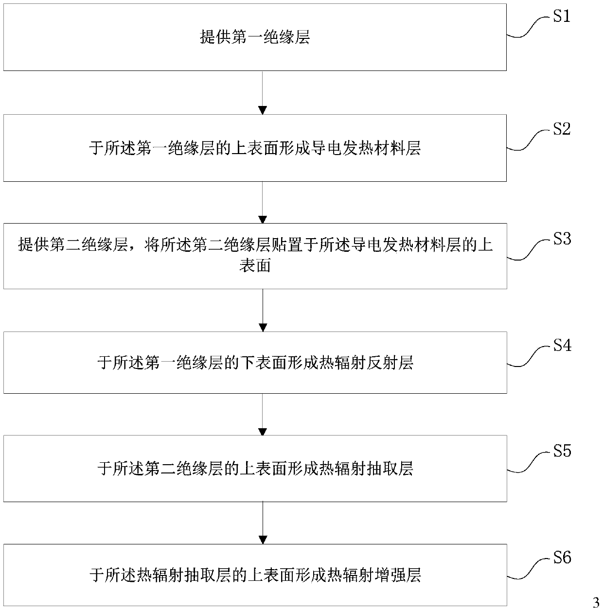
[0060] Please figure 1, the present embodiment provides a method for manufacturing an electrothermal film assembly, the method for manufacturing an electrothermal film assembly includes the steps of:

[0061] 1) providing a first insulating layer;

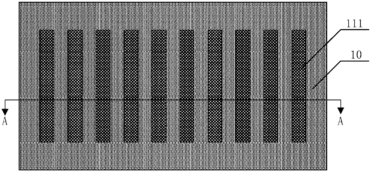
[0062] 2) forming a conductive heating material layer on the upper surface of the first insulating layer;

[0063] 3) providing a second insulating layer, and affixing the second insulating layer on the upper surface of the conductive heating material layer;

[0064] 4) forming a heat radiation reflective layer on the lower surface of the first insulating layer;

[0065] 5) forming a heat radiation extraction layer on the upper surface of the second insulating layer;

[0066] 6) Forming a thermal radiation enhancing layer on the upper surface of the thermal radiation extraction layer.

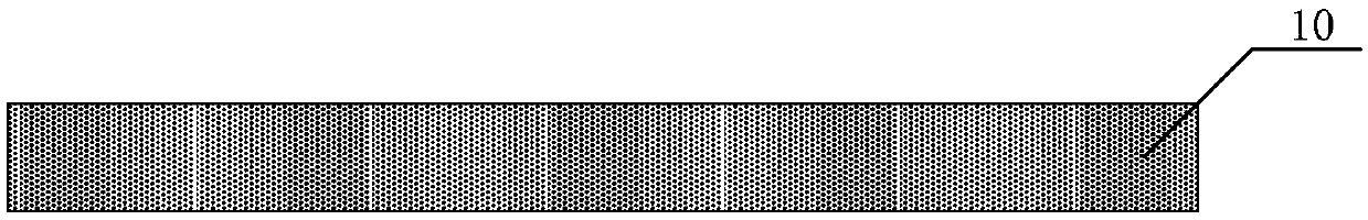
[0067] In step 1), see figure 1 In the S1 step, the first insulating layer 10 is provided.

[0068] As an example, the first insulating layer...

Embodiment 2

[0111] Please combine Figure 2 to Figure 9 read on Figure 10 to Figure 12 , this embodiment also provides an electrothermal film assembly, the electrothermal film assembly includes: a first insulating layer 10; a conductive heating material layer 11, the conductive heating material layer 11 is located on the upper surface of the first insulating layer 10; The second insulating layer 12, the second insulating layer 12 covers at least the upper surface of the conductive heating material layer 11; the heat radiation reflecting layer 13, the heat radiation reflecting layer 13 is located under the first insulating layer 10 Surface; thermal radiation extraction layer 14, the thermal radiation extraction layer 14 is located on the upper surface of the second insulating layer 12; thermal radiation enhancement layer 15, the thermal radiation enhancement layer 15 is located on the thermal radiation extraction layer 14 surface.

[0112] As an example, the first insulating layer 10 ma...

Embodiment 3

[0137] Please combine Figure 2 to Figure 9 read on Figure 10 to Figure 12 , this embodiment also provides an electric heating device, the electric heating device includes the electrothermal film assembly as described in Embodiment 2, the heat radiation reflective layer 13 and the heat radiation extraction in the electrothermal film assembly Layer 14 is connected to the ground wire of the power supply. For the specific structure of the electrothermal film assembly, please refer to Embodiment 2, which will not be repeated here.

[0138] As an example, the electric heating device may include, but not limited to, electric blankets, floor heaters, electric seat cushions, electric floor mats, electric ceilings, electric walls, and the like.

[0139] As mentioned above, the electrothermal film assembly and its manufacturing method of the present invention, the electrothermal film assembly includes: a first insulating layer; a conductive heating material layer located on the upper ...


PUM

PropertyMeasurementUnit
glass transition temperatureaaaaaaaaaa
thicknessaaaaaaaaaa
thicknessaaaaaaaaaa

Abstract

The invention provides an electrothermal film assembly and a manufacturing method thereof. The electrothermal film assembly comprises a first insulating layer, a conductive heat-generating material layer arranged on the upper surface of the first insulating layer, a second insulating layer at least covering the upper surface of the conductive heat-generating material layer, a thermal-radiation reflecting layer arranged at the lower surface of the first insulating layer, a thermal-radiation extracting layer arranged at the upper surface of the second insulating layer, and a thermal-radiation enhancing layer arranged at the upper surface of the thermal-radiation extracting layer. The electrothermal film assembly has the high thermal-radiation efficiency and thermal extraction efficiency; andthe loss of electric energy is reduced effectively. According to the electrothermal film assembly, the outer side of the electrothermal film assembly is packaged plastically by the insulating layers,so that the electrothermal film assembly has the stable electric heating function, the good insulating performance and high safety. Meanwhile, since the thermal-radiation reflecting layer and the thermal-radiation extracting layer in the electrothermal film assembly can be connected with the ground wire of the power source, the capacitance effect formed by the electrothermal film assembly and theoutside can be eliminated and thus the good safe and electric leakage prevention effects are realized.

Description

technical field [0001] The invention belongs to the field of electric heating technology, and in particular relates to an electric heating film component and a manufacturing method thereof. Background technique [0002] At present, the traditional indoor heating is mainly divided into water, steam heating and electrothermal film heating. Among them, the electrothermal film heating method is obviously more popular because of its advantages of less investment, simple maintenance, independent temperature control, and rapid heating. However, the existing electric heating film has the problems of low heat radiation efficiency and heat extraction efficiency, and large power loss; at the same time, since the electric heating film is usually placed under the floor, inside the wall or above the ceiling to obtain a soft indoor temperature rise effect , The front and back sides of the electric heating film will have a capacitive effect with the floor, wall or ceiling in contact with it...

Claims


Application Information

Patent Timeline
Patent Type & Authority Applications(China)
IPC IPC(8): H05B3/20H05B3/02H05B3/14B32B3/08B32B15/08
CPCH05B3/20B32B3/085B32B15/08B32B2307/206B32B2307/30H05B3/02H05B3/145
Inventor 宋世耀李智
Owner 河南问暖电子科技有限公司
Why Eureka
Try Eureka