
Cleaning device with full-width cleaning mobile window structure

A mobile window and equipment technology, applied in the field of clean equipment with a structure that can clean the entire width of the window, can solve the problems of waste of energy consumption, increase the waiting time of the test, etc., to reduce the waste of energy consumption, improve the cleanliness of the cabinet, The effect of improving work efficiency

Pending Publication Date: 2019-03-29
苏州安泰空气技术有限公司
View PDF21 Cites 0 Cited by
  • Summary
  • Abstract
  • Description
  • Claims
  • Application Information

AI Technical Summary

Problems solved by technology

This is bound to be detrimental to the use of energy consumption, but if the fan is turned off, self-cleaning in the early stage is required, which is also a waste of energy consumption and increases the waiting time of the test

Method used


Image

  • Cleaning device with full-width cleaning mobile window structure
  • Cleaning device with full-width cleaning mobile window structure
  • Cleaning device with full-width cleaning mobile window structure

Examples


Embodiment 1

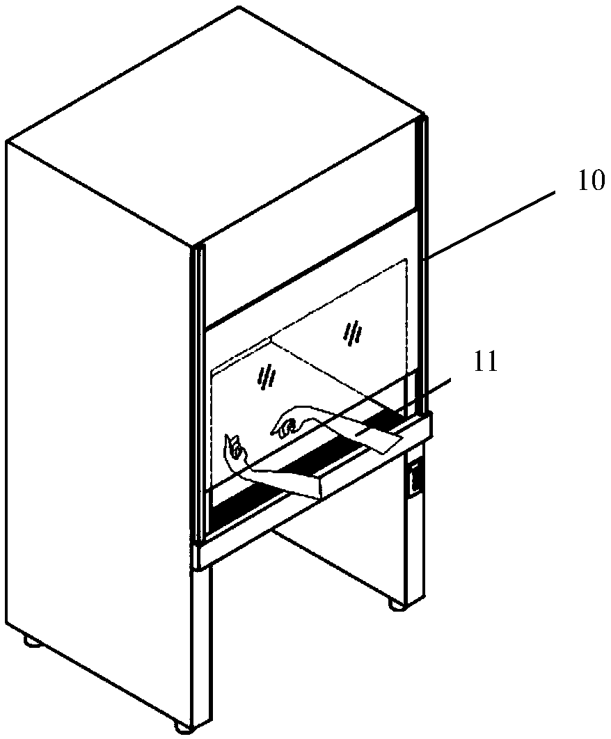
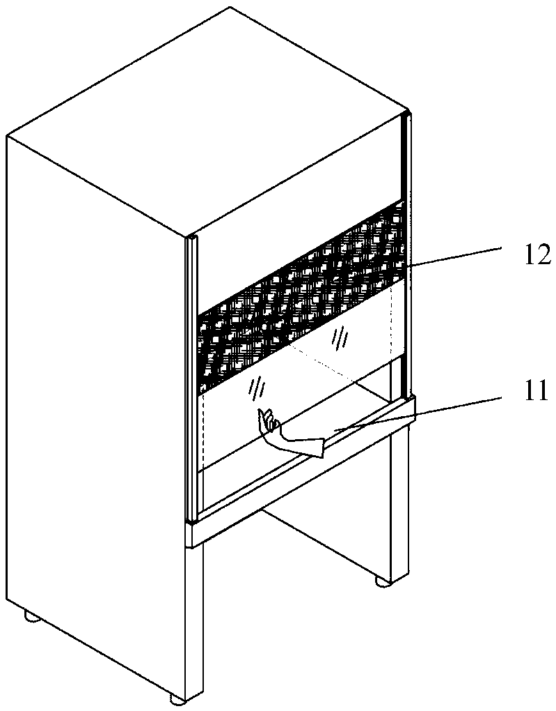
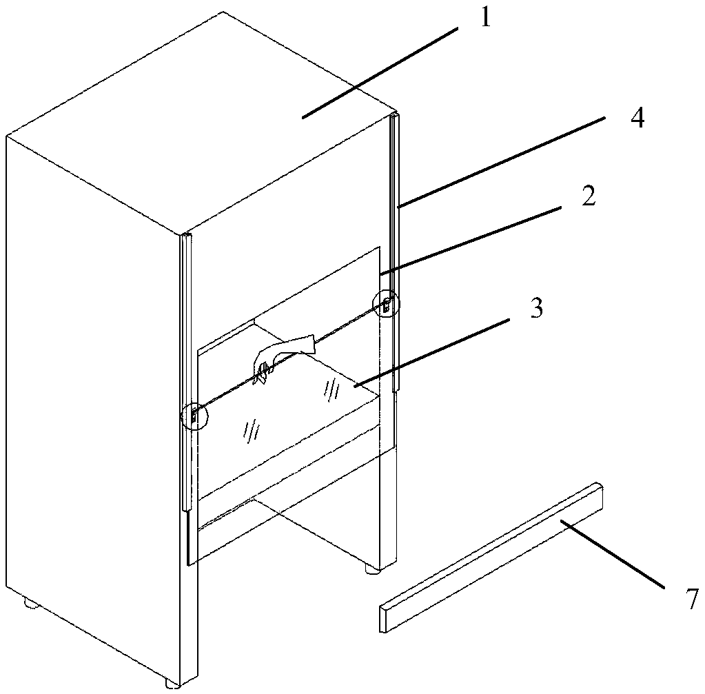
[0031] Embodiment one: see Figure 3-6 As shown, a cleaning device with a movable window structure that can clean the entire width includes a device body 1, an operation window 2 is provided on one side of the device body 1, and a glass panel 3 that can move up and down is provided at the corresponding operation window 2. The device body 1 is provided with an air flow system, the left and right sides of the glass panel 3 are provided with slideways 4, and a limit block 5 is provided near the middle of the slideway 4, and a stopper is provided on the glass panel 3 6. The bottom end of the block 6 cooperates with the limit block 5; a safety baffle 7 is provided under the glass panel 3 and at the end of the slideway 4, and the safety baffle 7 is connected with the device The body 1 is connected through a detachable structure.

[0032] Such as Figure 5 As shown, a block 6 is respectively provided at the left and right ends of the upper edge of the glass panel. plate 8, the sto...

Embodiment 2

[0037] Embodiment 2: A cleaning device with a structure that can clean the entire width of the movable window. In this embodiment, its basic structure is the same as that of Embodiment 1. The difference is that the airflow system also includes an image sensor and a window moving control device. , the image sensor collects the activity state of the person, and when the collection of no portrait information exceeds the set time, the information is sent to the window-moving control device, and the window-moving control device drives the glass panel to move down and close, and switches the wind speed; After the portrait information, the window moving control device drives the glass panel to move up to restore the normal wind speed.

[0038] In this embodiment, through the collection of portraits, the position of the operator is judged in real time, and the glass panel is automatically closed and opened by the window moving control device without manual intervention by personnel, wh...


PUM


Abstract

The invention discloses a cleaning device with a full-width cleaning mobile window structure. The device comprises a device body, one side surface of the device body is provided with an operation window, a glass plate which can move up and down is arranged at a position corresponding to the operation window, an airflow system is arranged in the device body, a slide way is arranged at the left sideand the right side of the glass plate, a limiting block is arranged near the middle part of the slide way, the glass plate is provided with a stopping block, and the bottom end of the stopping blockis matched with the limiting block; and a safety baffle plate is arranged under the glass plate and located at the tail end of the slide way, and the safety baffle plate is connected with the device body through a detachable structure. The cleanliness of the cleaning device is further improved by controlling the movement of the glass plate, and the rotational speed of a fan is adjusted to reduce the energy consumption in order to achieve the environmental protection requirements of energy saving and emission reduction.

Description

technical field [0001] The invention relates to the technical field of cleaning equipment, in particular to a cleaning equipment with a movable window structure capable of cleaning the entire width. Background technique [0002] As one of the clean equipment, the dust-free workbench is an air purification equipment that provides a local dust-free and sterile working environment, and can artificially control the emission of polluted air in the work area through a special filter channel to avoid It is a safe dust-free workbench for microorganisms, which is harmful to people and the environment. It is widely used in medical and health, biopharmaceutical, food, medical science experiments, optics, electronics, sterile room experiments and other scientific research and production departments that require a partially clean and sterile working environment. [0003] Usually, the dust-free workbench includes a hollow cabinet to form an operation room. The cabinet is equipped with an...

Claims


Application Information

Patent Timeline
Patent Type & Authority Applications(China)
IPC IPC(8): B01L1/00G01D21/02
CPCG01D21/02B01L1/00
Inventor 陈旭东江尧顾中秋
Owner 苏州安泰空气技术有限公司
Learn More