
Automatic punching forming processing equipment for folding pin shaft barrel and application method

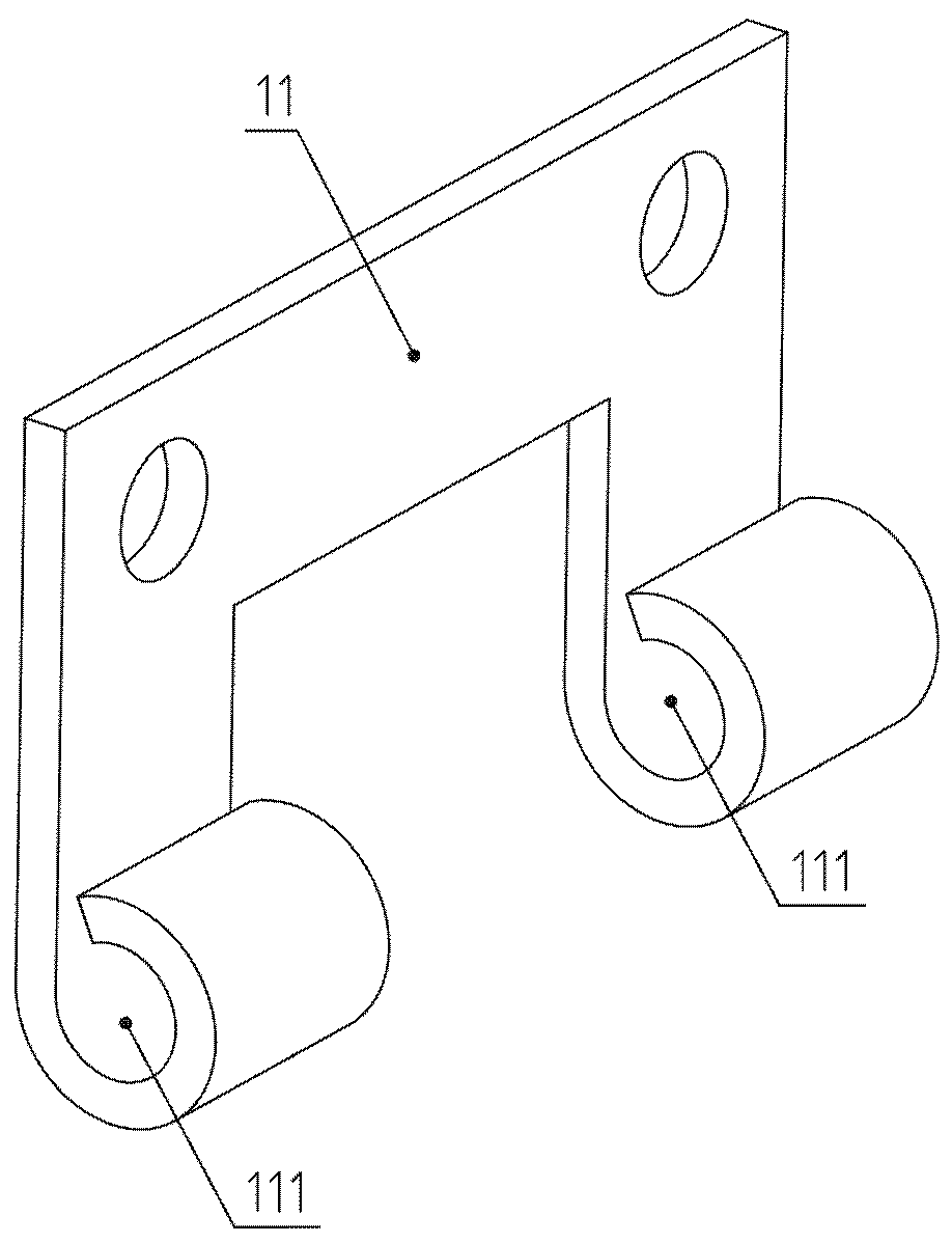
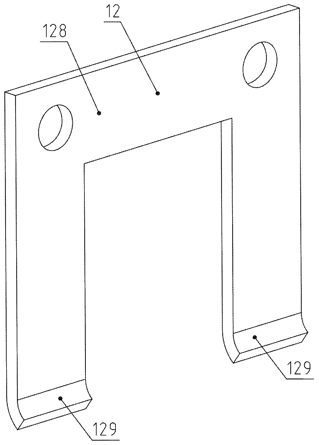
A stamping forming and processing equipment technology, applied in the direction of metal processing equipment, forming tools, manufacturing tools, etc., can solve the problems of hand injury, high risk, injury, etc.

Inactive Publication Date: 2019-03-29
杜宗英
View PDF7 Cites 0 Cited by
  • Summary
  • Abstract
  • Description
  • Claims
  • Application Information

AI Technical Summary

Problems solved by technology

[0006] The danger of manually placing the folding blank is very high. If one is not careful, the upper mold has been punched down before the hand can leave, which will cause great damage to the hand, and more serious hand disabilities. The higher the work efficiency, the more workers will The more tired you are, the more chances you have to cause injury
The work efficiency of manual feeding is also relatively low, and the fatigue of workers leads to lower efficiency

Method used


Image

  • Automatic punching forming processing equipment for folding pin shaft barrel and application method
  • Automatic punching forming processing equipment for folding pin shaft barrel and application method
  • Automatic punching forming processing equipment for folding pin shaft barrel and application method

Examples


Embodiment

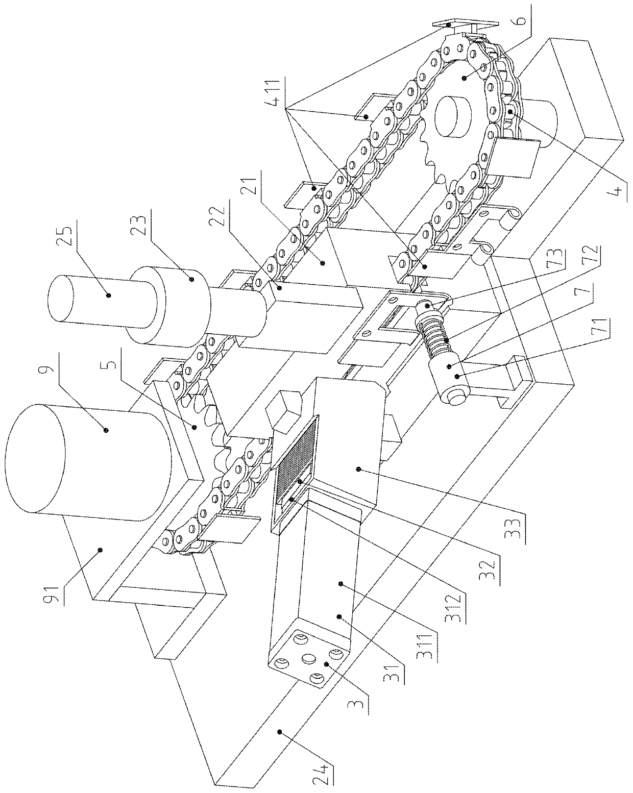
[0048] Example: see Figure 1 to Figure 17 .

[0049] A processing equipment for automatic stamping and forming of a folding pin cylinder, comprising an upper mold 22 and a lower mold 21; the bottom of the lower mold 21 is fixedly connected to a workbench 24, and the lower mold 21 is provided with a front-facing facade, and The lower part is provided with an arc groove; the upper part of the upper die 22 is fixedly connected with the working shaft handle 25 of the press, and the upper die 22 is plate-shaped;

[0050] It is characterized in that it also includes a material warehouse component 3, a transmission chain 4, a driving sprocket 5, a passive sprocket 6, a pressing component 7, an intermediate pressure relief type three-position five-way solenoid valve 8 and a motor 9;

[0051] The facade of the lower mold 21 is divided into two parts, the left side is the vertical feeding part 211, the right side is the vertical stamping part 213, the arc groove is divided into the le...


PUM


Abstract

The invention belongs to the technical field of hardware equipment, and relates to automatic punching forming processing equipment for a folding pin shaft barrel and an application method. A material-library air cylinder pushes folding blanks to transversely move backwards until the folding blanks are attached to a vertical-face feeding part, and a motor drives a transmission chain to do intermittent movement in a T-shaped groove. When the motor is stopped, a middle pressure-relief-type three-position and five-way electromagnetic valve is reversed and is reversed to a left position, and a pressing-plate pressing face presses the folding blanks; meanwhile, an upper die plunges down, punching-station folding blanks are converted into folding finished products. When the transmission chain transversely moves, the folding finished products located on a vertical-face punching part are pushed by pushing vertical faces and leave a lower die, and to-be-out-warehoused-station folding blanks arepushed by the pushing vertical faces to be located on the vertical-face punching part. A spring presses a pressing pin, and the spherical face of the pressing pin presses the plane parts of the punching-station folding blanks. By means of the automatic punching forming processing equipment for the folding pin shaft barrel and the application method, feeding and demolding can be automatically carried out, the efficiency is high, persons stand in the distance and operate, and do not need to touch the folding blanks with the hands, and the risk is small.

Description

technical field [0001] The invention belongs to the technical field of hardware processing equipment, and relates to a hinge forming processing equipment and a use method, in particular to an automatic stamping forming processing equipment and a use method of a hinge pin cylinder. Background technique [0002] The hinge used in the field of hardware technology includes two hinges and a pin shaft, wherein the first hinge is formed by rolling the bottom two sides of an "n"-shaped steel plate into a pin cylinder, and the second hinge is It is formed by rolling the bottom end of a "T"-shaped steel plate into a pin shaft tube, and the pin shaft penetrates into the pin shaft tubes of the two folding pages to form a hinge to form a hinge. [0003] Take the first fold as an example to illustrate its traditional manufacturing process. [0004] The folding blank is completed on a punching machine, which is punched into an "n" shape on a piece of steel plate master material, and the b...

Claims


Application Information

Patent Timeline
Patent Type & Authority Applications(China)
IPC IPC(8): B21D22/06B21D37/10
CPCB21D22/06B21D37/10
Inventor 不公告发明人
Owner 杜宗英
Learn More