Eureka AIR delivers breakthrough ideas for toughest innovation challenges, trusted by R&D personnel around the world.

Wear-resisting ball cooling discharging device

A technology of a discharge device and a cooling device, which is applied in the field of wear-resistant ball production, and can solve problems such as uneven cooling of steel balls

Active Publication Date: 2019-03-29
新疆闽龙耐磨材料有限公司
View PDF6 Cites 0 Cited by
  • Summary
  • Abstract
  • Description
  • Claims
  • Application Information

AI Technical Summary

Problems solved by technology

[0005] The purpose of the present invention is to provide a wear-resistant ball cooling and discharging device, which solves the problem of uneven cooling of steel balls in the prior art

Method used


Image

  • Wear-resisting ball cooling discharging device
  • Wear-resisting ball cooling discharging device
  • Wear-resisting ball cooling discharging device

Examples


Embodiment Construction

[0027] The present invention will be described in further detail below by means of specific embodiments:

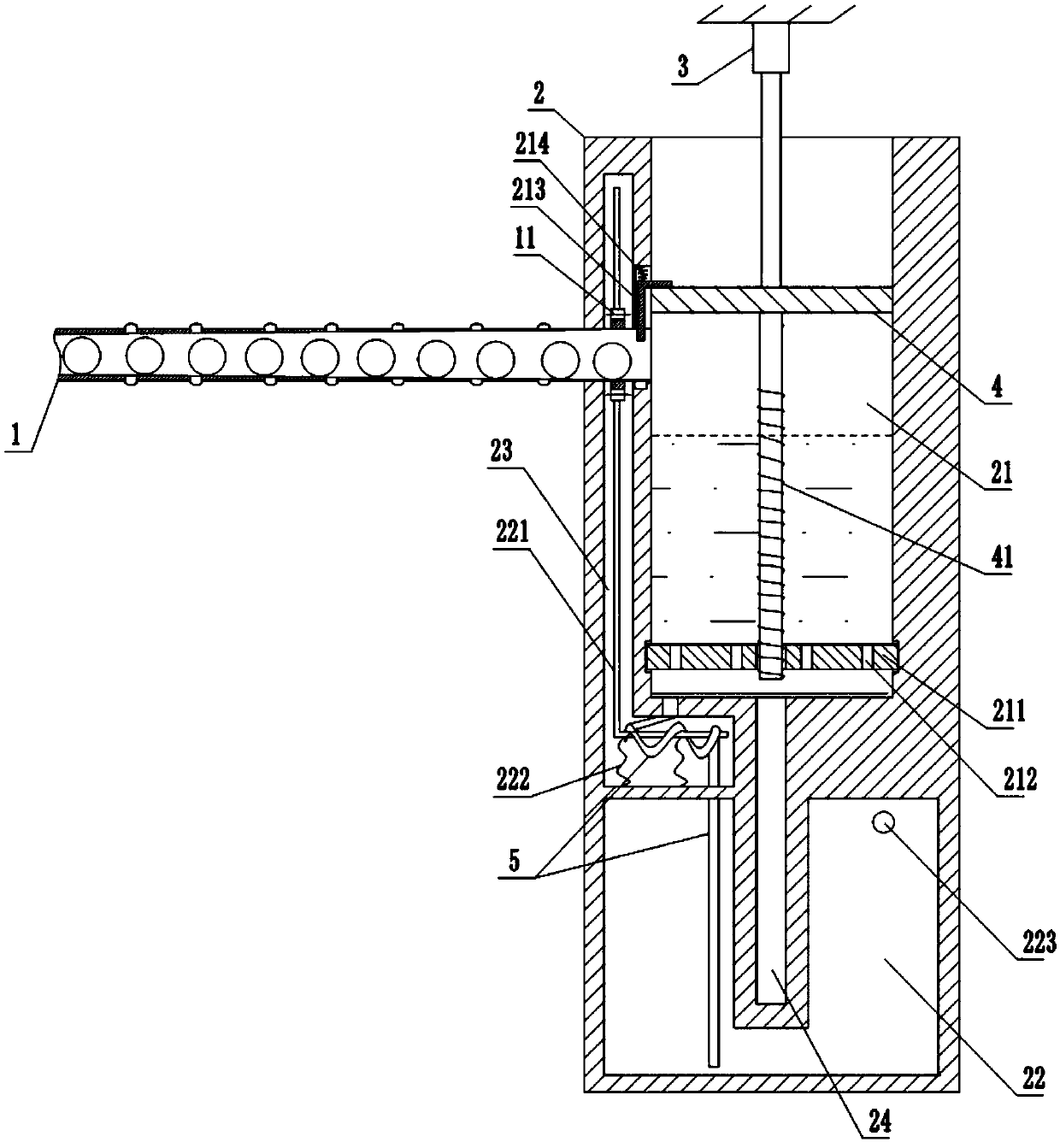
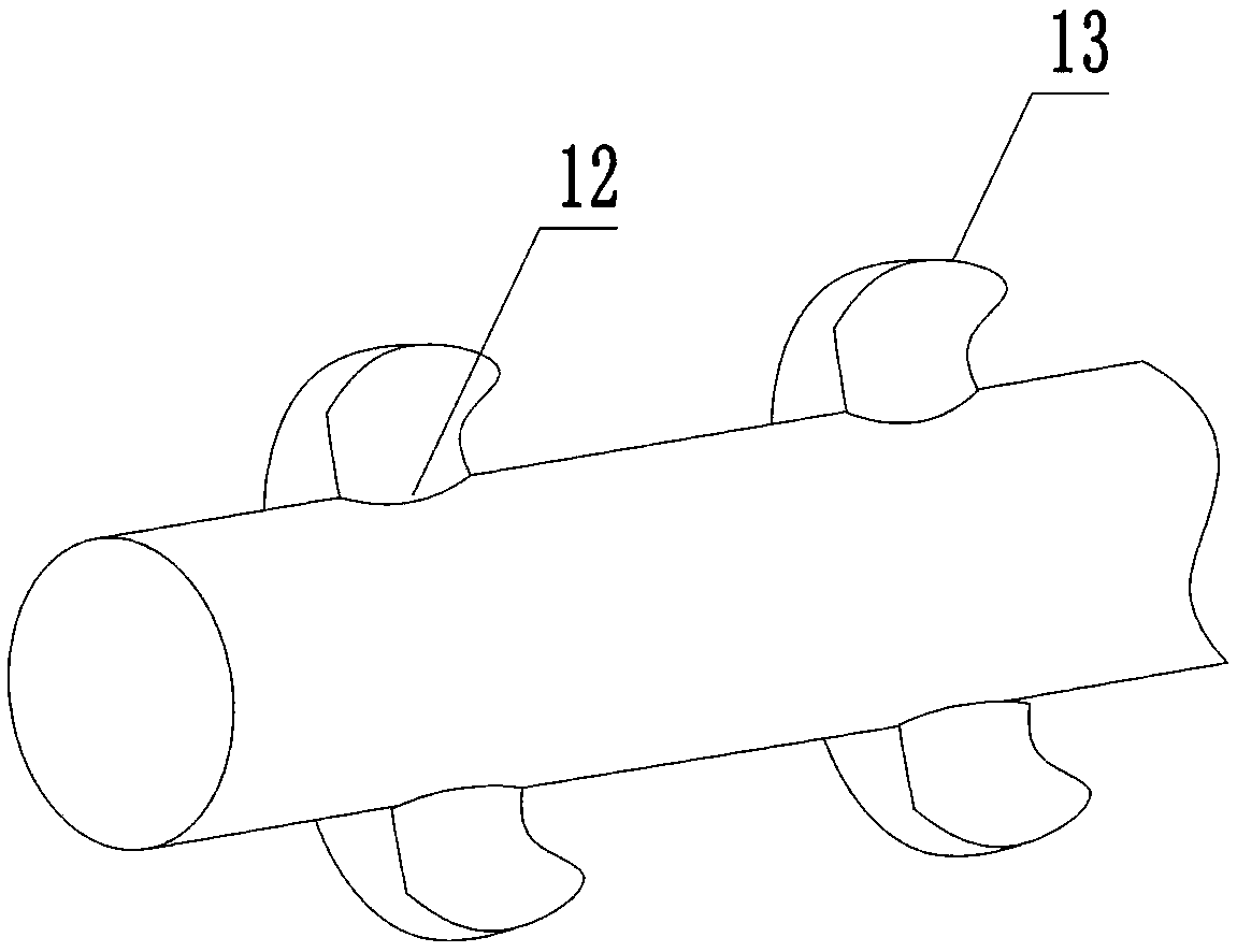
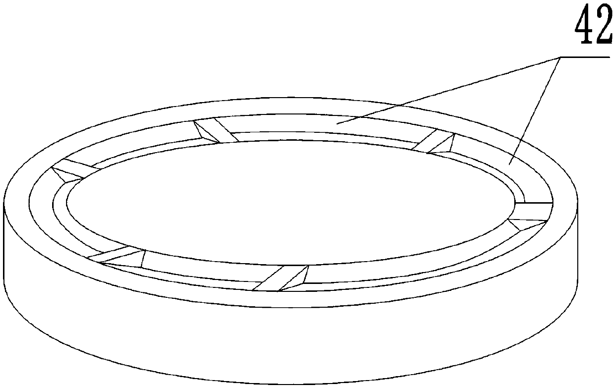
[0028] The reference signs in the accompanying drawings of the specification include: feed pipe 1, ring gear 11, heat dissipation hole 12, air collecting ear 13, cooling device 2, processing chamber 21, rotating disc 211, water leakage hole 212, door panel 213, reset member 214 , Cooling chamber 22, rack 221, elastic member 222, vent hole 223, power chamber 23, stroke channel 24, hydraulic cylinder 3, piston 4, screw rod 41, arc port 42, rubber pad 421, support plate 4211, spring member 4212, water pipe 5.

[0029] Such as figure 1 , figure 2 , image 3 , Figure 4 with Figure 5 Shown, in order to achieve the above object, basic scheme of the present invention is as follows:

[0030] A wear-resistant ball cooling discharge device, comprising a feed pipe 1 and a cooling device 2, the feed pipe 1 communicates with the upper part of the cooling device 2, and the feed...


PUM


Abstract

The invention relates to the technical field of wear-resisting ball manufacturing, in particular to a wear-resisting ball cooling discharging device. The wear-resisting ball cooling discharging devicecomprises a feeding tube and a cooling device, wherein the feeding tube is rotatably connected with the cooling device; the cooling device is internally provided with a machining cavity, a cooling cavity, a power cavity and a travel channel; a piston is slidably connected to the inner part of the machining cavity; a threaded rod is fixed to the lower part of the piston; a rotating disc driven torotate by the threaded rod is rotatably connected to the machining cavity; the threaded rod is capable of stretching into the travel channel; a door plate controlled by the piston to open is slidablyconnected to the cavity wall of the machining cavity; the door plate is provided with a position restoration piece which is used for restoration of the door plate; and the door plate is positioned atthe tube opening of the feeding tube; the feeding tube is provided with a gear ring, a rack used for meshing with the gear ring is slidably and internally connected to the power cavity; a water tube is arranged at the lower end of the rack in a winding mode; an elastic piece used for the restoration of the rack is arranged between the rack and the cavity wall of the power cavity; the water tube stretches into the cooling cavity; and a heat dissipation hole is formed in the tube wall of the feeding tube. According to the wear-resisting ball cooling discharging device, the problem that the cooling of steel balls is uneven in the prior art is solved.

Description

technical field [0001] The invention relates to the technical field of wear-resistant ball production, in particular to a wear-resistant ball cooling and discharging device. Background technique [0002] Wear-resistant ball is a kind of crushing medium used in ball mills, which is used to crush the materials in the mill. The production of wear-resistant balls is generally made by heating and melting iron into molten iron, injecting it into a mold, and forming wear-resistant balls after molding; then pushing the steel balls into a cooling pool to cool them down. [0003] The prior art has the following technical problems: [0004] The newly processed wear-resistant balls, due to the high heat, fall into the cooling pool in piles and gather in the cooling pool. The steel balls conflict with each other and cannot fully contact the soaking liquid. The cooling of the steel balls is uneven. The hardness of the steel ball is uneven. Contents of the invention [0005] The objec...

Claims


Application Information

Patent Timeline
IPC IPC(8): B22D30/00
CPCB22D30/00
Inventor 邵昌陈新寿陈作武陈家来陈炜彬
Owner 新疆闽龙耐磨材料有限公司
Why Eureka
Eureka Blog
Learn More