Eureka AIR delivers breakthrough ideas for toughest innovation challenges, trusted by R&D personnel around the world.

Straight knife sharpener

A knife grinder and grinding head technology, which is applied in the direction of grinding frame, grinding machine parts, grinding bed, etc., can solve the problems of low production efficiency, low efficiency, slow handling speed, etc., and achieve a simple structure Effect

Pending Publication Date: 2019-03-29
江苏贝斯特数控机械有限公司
View PDF0 Cites 8 Cited by
  • Summary
  • Abstract
  • Description
  • Claims
  • Application Information

AI Technical Summary

Problems solved by technology

Usually the grinding of straight knife is carried out by surface grinder or special straight knife grinder similar to surface grinder. To complete the grinding process, the straight knife can be placed on the electromagnetic chuck of the workbench for direct grinding when the plane of the cutter body is ground. The grinding of the cutting edge requires two clampings, the production efficiency is low, and the quality is not easy to guarantee; and during the grinding process, it is necessary to stop the machine and manually measure the relevant dimensions of the straight knife to be ground, and determine the feed amount according to the measurement results until the desired value is reached. The required size and precision, such a precision control method is greatly affected by the technical level of the operator, measurement errors, etc., the machining accuracy is difficult to guarantee, and the efficiency is also very low; The loading and unloading needs to be done manually by the operator, which is labor-intensive, slow in handling and low in efficiency

Method used


Image

  • Straight knife sharpener
  • Straight knife sharpener
  • Straight knife sharpener

Examples


Embodiment Construction

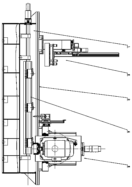
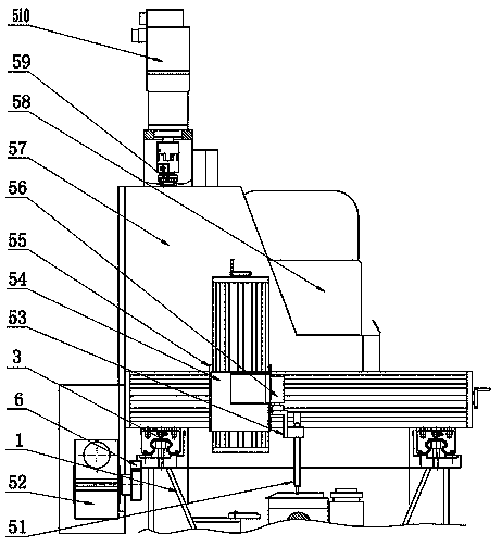
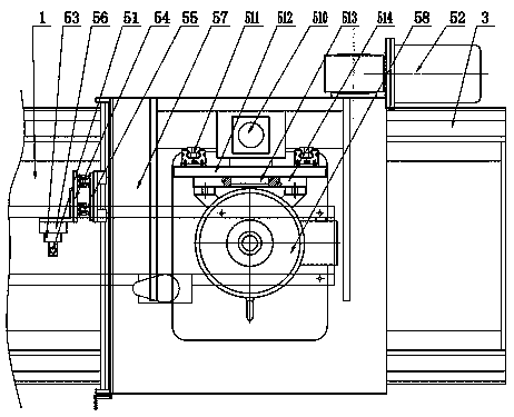
[0031] exist figure 1 In the straight knife sharpener shown, the straight knife sharpener includes a bed 1, a grinding head assembly 5 and a workbench assembly 4. The bed 1 is the basic supporting component of the entire straight knife sharpener, and the top of the bed 1 Two bed linear guide rail pairs 3 are respectively installed on the left and right sides of the surface, the workbench assembly 4 is located between the left and right bed linear guide rail pairs 3, and the grinding head assembly 5 is slidably supported on the bed body 1 by the two bed linear guide rail pairs 3 , On the lathe bed 1, there is also a gripping manipulator 2 slidably supported.

[0032] see Figure 4 , Figure 5 with Image 6 , the workbench assembly 4 includes a workbench body 42, on which an electromagnetic chuck 46 is fixedly installed, on the workbench body 42 is provided with a workbench rotating shaft 45, and the workbench rotating shaft 45 is arranged along the length direction of the wo...


PUM


Abstract

The invention discloses a straight knife sharpener comprising a lathe body, a grinding head assembly and a workbench assembly. Two lathe body linear guide rail pairs are arranged on the top face of the lathe body. The grinding head assembly is supported on the lathe body slidably by a grinding head movable base through the two lathe body linear guide rail pairs. A grinding head motor is installedon a grinding head sliding seat through a grinding head installing plate, and the grinding head sliding seat is driven by a grinding head feed motor and is slidably supported on the grinding head movable base. Position sensors are arranged on the grinding head movable base through vertical and transverse moving sliding seats and a detection driving device. The workbench assembly is located betweenthe left and right lathe body linear guide rail pairs. A workbench is supported on a lathe body in an oscillatory mode. A workpiece locating plate and a workpiece locating push arm are arranged on the two sides of a workbench body correspondingly. A grabbing manipulator is further slidably supported on the lathe body through the lathe body linear guide rail pairs and a side face linear guide railpair. Automatic feeding and discharging and automatic control of grinding precision can be achieved through the straight knife sharpener, a straight knife plane and a cutting edge bevel can be groundthrough one time of clamping, and production efficiency is high.

Description

technical field [0001] The invention relates to a metal cutting machine tool, in particular to a grinding machine used for grinding the plane and edge of a sheet-shaped straight knife. Background technique [0002] Straight knives are a kind of sheet-shaped and long strip-shaped knives, which are widely used in papermaking, printing, textile, fiber, food, forestry, plastic, wood and other industries. In the manufacturing process of the straight knife, the plane of the knife body and the inclined surface of the edge of the straight knife must be ground to ensure the sharpness and straightness of the knife edge and the consistency of the size. Usually the grinding of straight knife is carried out by surface grinder or special straight knife grinder similar to surface grinder. To complete the grinding process, the straight knife can be placed on the electromagnetic chuck of the workbench for direct grinding when the plane of the cutter body is ground. The grinding of the cutt...

Claims


Application Information

Patent Timeline
IPC IPC(8): B24B3/36B24B41/00B24B49/04B24B41/02B24B47/20B24B47/12
CPCB24B3/36B24B41/005B24B41/02B24B47/12B24B47/20B24B49/045
Inventor 张小季张明
Owner 江苏贝斯特数控机械有限公司
Why Eureka
Eureka Blog
Learn More