Non-knife-mark die cutting method for polyimide film product and die cutting device

A polyimide film and die-cutting technology, which is applied in metal processing and other directions, can solve the problems that the polyimide film cannot be peeled off, the size of the polyimide film is small, and the difficulty is large, so as to facilitate automatic lamination and guarantee Product integrity, the effect of reducing precision requirements

Active Publication Date: 2019-03-29
上海昊佰智造精密电子股份有限公司
View PDF15 Cites 12 Cited by
  • Summary
  • Abstract
  • Description
  • Claims
  • Application Information

AI Technical Summary

Problems solved by technology

[0003] 1. The size of the polyimide film used for automatic bonding is small (3mm×2mm×0.2mm). After multiple polyimide films are simultaneously die-cut on the release film tape, the outer frame needs to be The waste and the waste between multiple polyimide films are discharged, but because the polyimide film is small, and there is a layer of double-sided adhesive between the polyimide film and the release film material belt, the waste discharge At this time, the double-sided adhesive will stick back, causing the polyimide film to be discharged together with the waste, resulting in the lack of products on the material belt, so it is more difficult to directly discharge the waste on the release film material belt;
[0004] 2. When multiple polyimide films are die-cut directly on the release film tape, it is difficult to accurately control the depth of the die-cutting edge, resulting in residual knife marks on the release film tape. If the knife marks are too deep, Then, during automatic lamination, the robotic arm cannot peel off the polyimide film from the release film tape smoothly;
[0005] 3. If the position of the polyimide film on the release film tape deviates, the automatic laminating device will not be able to recognize the polyimide film, so it should be ensured that the edge of the release film tape is straight and polyimide The distance deviation between the imide film and the edge of the release film tape should be less than ±0.2mm, which further increases the difficulty of die-cutting

Method used


Image

  • Non-knife-mark die cutting method for polyimide film product and die cutting device
  • Non-knife-mark die cutting method for polyimide film product and die cutting device
  • Non-knife-mark die cutting method for polyimide film product and die cutting device

Examples


Embodiment

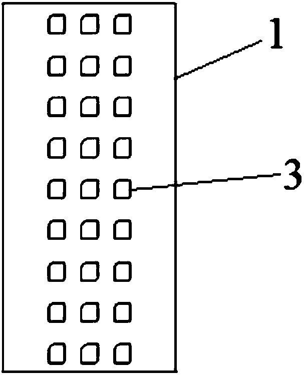
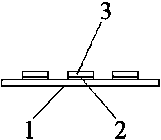
[0052] A kind of non-knife printing die-cutting method of polyimide film product, such as figure 1 , figure 2 Shown, polyimide film product comprises release film material band 1, a plurality of polyimide films 3 and is arranged on the double-sided adhesive tape 2 between polyimide film 3 and release film material band 1, mold The cutting method specifically includes the following steps:

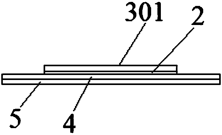
[0053] 1) if image 3 As shown, the polyimide film strip 301 is attached to the auxiliary strip, the auxiliary strip includes the first protective film 5 and the auxiliary release film 4 attached to the first protective film 5, double-sided adhesive tape 2 It is located between the polyimide film strip 301 and the auxiliary release film 4 . Such as Figure 4 As shown, the polyimide film 3 is die-cut on the polyimide film strip 301; a pair of word lines 7 are die-cut on the auxiliary release film 4 at the same time, and the word line 7 is along the auxiliary release film 4. The length d...


PUM


Abstract

The invention relates to a non-knife-mark die cutting method for a polyimide film product and a die cutting device. The non-knife-mark die cutting method specifically comprises the following steps that (1) a polyimide film material strip is attached to an auxiliary material strip, and then polyimide films are formed on the polyimide film material strip in a die cutting mode; (2) a second protecting film is attached to the polyimide film material strip, and then waste on the auxiliary material strip and the polyimide film material strip is discharged; and (3) a release film material strip is attached to the polyimide films and trimmed, and then waste on the second protecting film and the release film material strip is discharged. The die cutting device comprises an auxiliary material stripfeeding unit, a first die cutting unit, a second protecting film feeding unit, a first waste discharging unit, a release film material strip feeding unit, a second die cutting unit and a second wastedischarging unit. Compared with the prior art, no knife mark remains on the release film material strip of a final product, the integrity of the product on the material strip is good, and machining iseasy.

Description

technical field [0001] The invention belongs to the technical field of polyimide films, and relates to a knife-free die-cutting method and a die-cutting device for polyimide film products. Background technique [0002] With the continuous development of science and technology, the application of automated processing methods is becoming more and more common. In the electronics industry, the process of attaching polyimide film (PI film) to electronic products has been automated. In the process of automatic fitting, there are the following problems: [0003] 1. The size of the polyimide film used for automatic bonding is small (3mm×2mm×0.2mm). After multiple polyimide films are simultaneously die-cut on the release film tape, the outer frame needs to be The waste and the waste between multiple polyimide films are discharged, but because the polyimide film is small, and there is a layer of double-sided adhesive between the polyimide film and the release film material belt, the...

Claims


Application Information

Patent Timeline
Patent Type & Authority Applications(China)
IPC IPC(8): B26F1/38B26F1/44B26D7/00B26D7/18
CPCB26D7/00B26D7/18B26F1/38B26F1/44B26D2007/0012Y02P70/10
Inventor 蒋建国杜月华
Owner 上海昊佰智造精密电子股份有限公司
Why Eureka
Try Eureka