
One-way resetting mechanism for locomotive brake controller and brake controller

A technology of brake controller and reset mechanism, which is applied to the operating mechanism of railway vehicle brake, railway braking system, manual starting device, etc. Easy to adjust, easy to install and disassemble, high reliability

Active Publication Date: 2019-03-29
ZHUZHOU ELECTRIC LOCOMOTIVE CO
View PDF7 Cites 0 Cited by
  • Summary
  • Abstract
  • Description
  • Claims
  • Application Information

AI Technical Summary

Problems solved by technology

After long-term use, the tension spring in the one-way reset mechanism is prone to breakage at the hook at its end and cannot be reset, which leads to the failure of the one-way reset mechanism and causes "overcharging" of the large brake unit of the locomotive brake controller "Relief" bit signal loss of bit and small gate unit, low working reliability
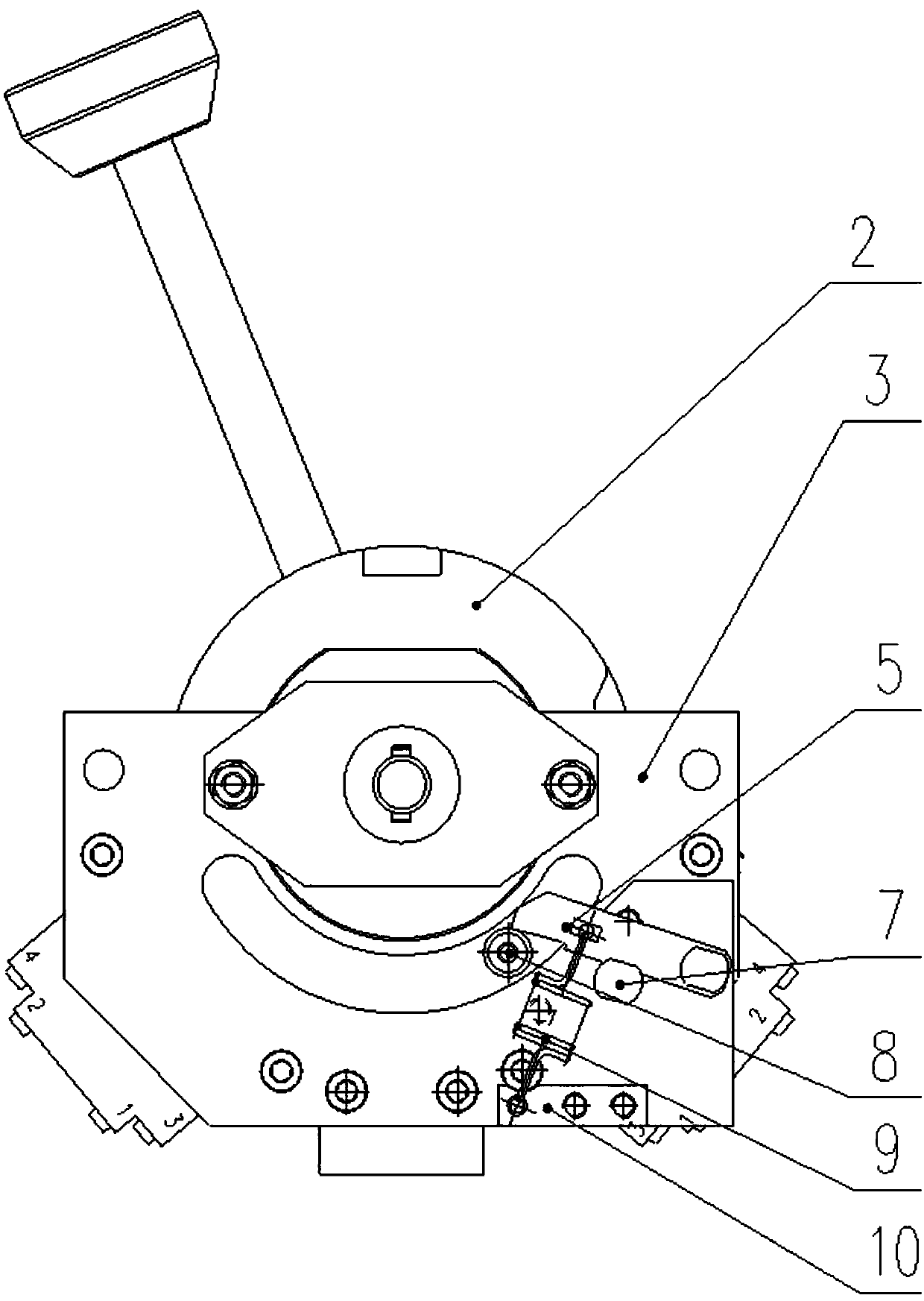
[0006] Second, the parts of the one-way reset mechanism corresponding to the large brake unit and the small brake unit installed on the same brake controller have directionality, and some parts cannot be interchanged, which increases the difficulty and cost of parts production and accessories management
[0007] Third, the one-way reset mechanism is a non-integral module structure, which takes up a lot of space, and the cumulative tolerance difference after the assembly of multiple parts is relatively large, which requires a wealth of process assembly skills and time-consuming adjustments

Method used


Image

  • One-way resetting mechanism for locomotive brake controller and brake controller
  • One-way resetting mechanism for locomotive brake controller and brake controller
  • One-way resetting mechanism for locomotive brake controller and brake controller

Examples


Embodiment Construction

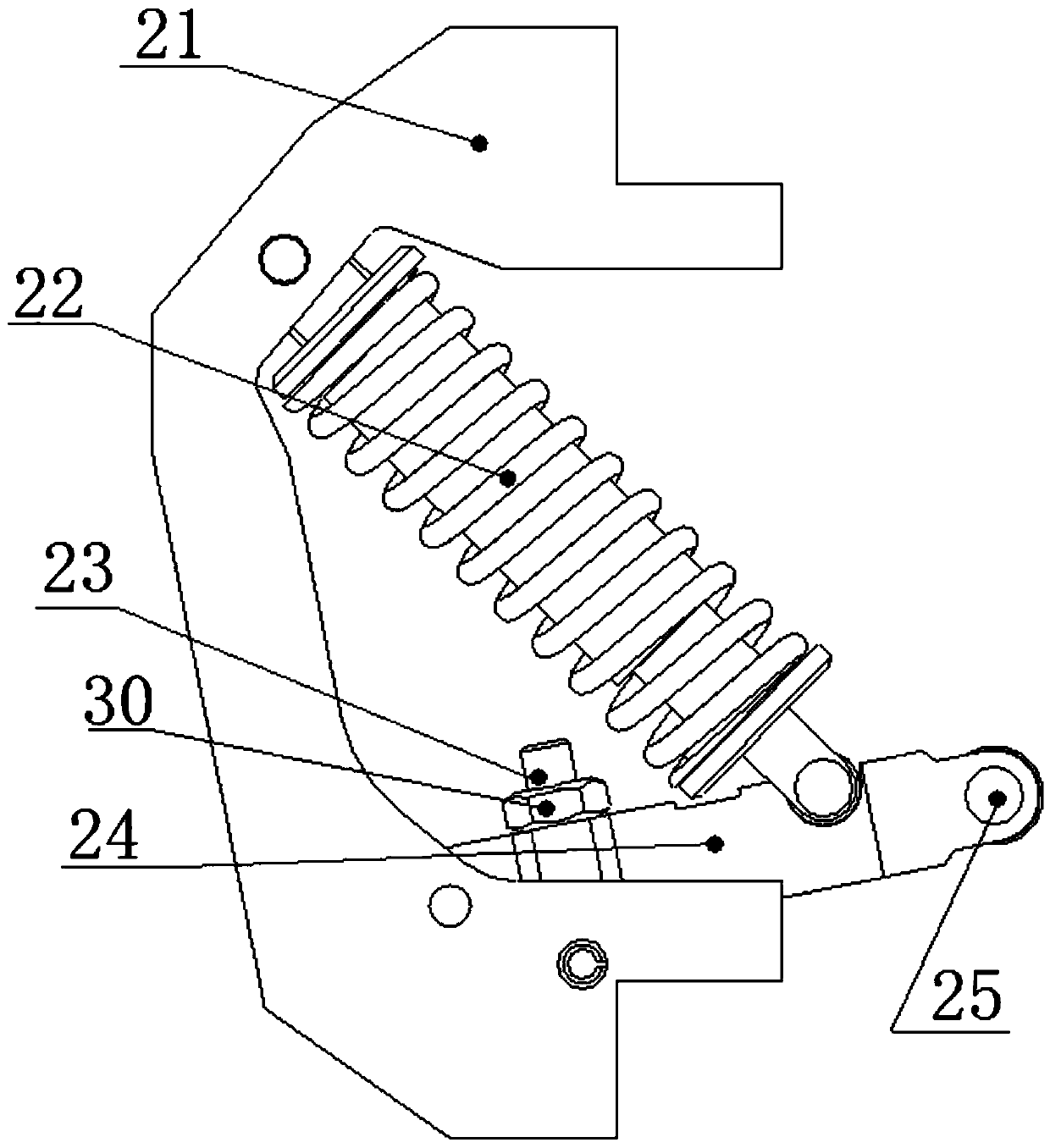
[0029] Such as Figure 3 to Figure 5 As shown, the one-way reset mechanism for the locomotive brake controller includes a reset frame 21, elastic mechanisms 22, 26, 27, and a reset lever 24; one end of the reset lever 24 is hinged with the reset frame 21, and the other end of the reset lever 24 is hinged with the roller 25. ; One end of the elastic mechanism 22,26,27 is hinged with the reset frame 21, and the other end of the elastic mechanism 22,26,27 is hinged with the middle section of the reset lever 24.

[0030] Described elastic mechanism 22,26,27 comprises reset stage clip 22, guide cylinder 27 and guide rod 26, and one end of guide rod 26 stretches in guide cylinder 27 from guide cylinder 27 one ends, and the other end of guide rod 26 and reset lever 24 The middle section is hinged, and the other end of the guide cylinder 27 is hinged with the reset frame 21; the reset compression spring 22 is sleeved outside the guide rod 26 and the guide cylinder 27; The position po...


PUM


Abstract

The invention discloses a one-way resetting mechanism for a locomotive brake controller and the brake controller. The one-way resetting mechanism comprises a resetting frame, an elastic mechanism anda resetting lever; one end of the resetting lever is hinged to the resetting frame, and the other end of the resetting lever is hinged to a roller; one end of the elastic mechanism is hinged to the resetting frame, and the other end of the elastic mechanism is hinged to a middle portion of the resetting lever; the elastic mechanism includes a resetting compression spring, a guide cylinder and a guide rod, wherein one end of the guide rod extends into the guide cylinder from one end of the guide cylinder, the other end of the guide rod is hinged to the middle section of the resetting lever, andthe other end of the guide cylinder is hinged to the resetting frame; the resetting compression spring sleeves the guide rod and the guide cylinder; the outer wall of the guide rod is provided with afirst limiting portion limiting one end of the resetting compression spring, and the outer wall of the guide cylinder is provided with a second limiting portion for limiting the other end of the resetting compression spring. The one-way resetting mechanism has high working reliability, good interchangeability, compact structure, capable of making an adjustment stroke easy to adjust, easy to mountand dismount and good in maintenance-free performance.

Description

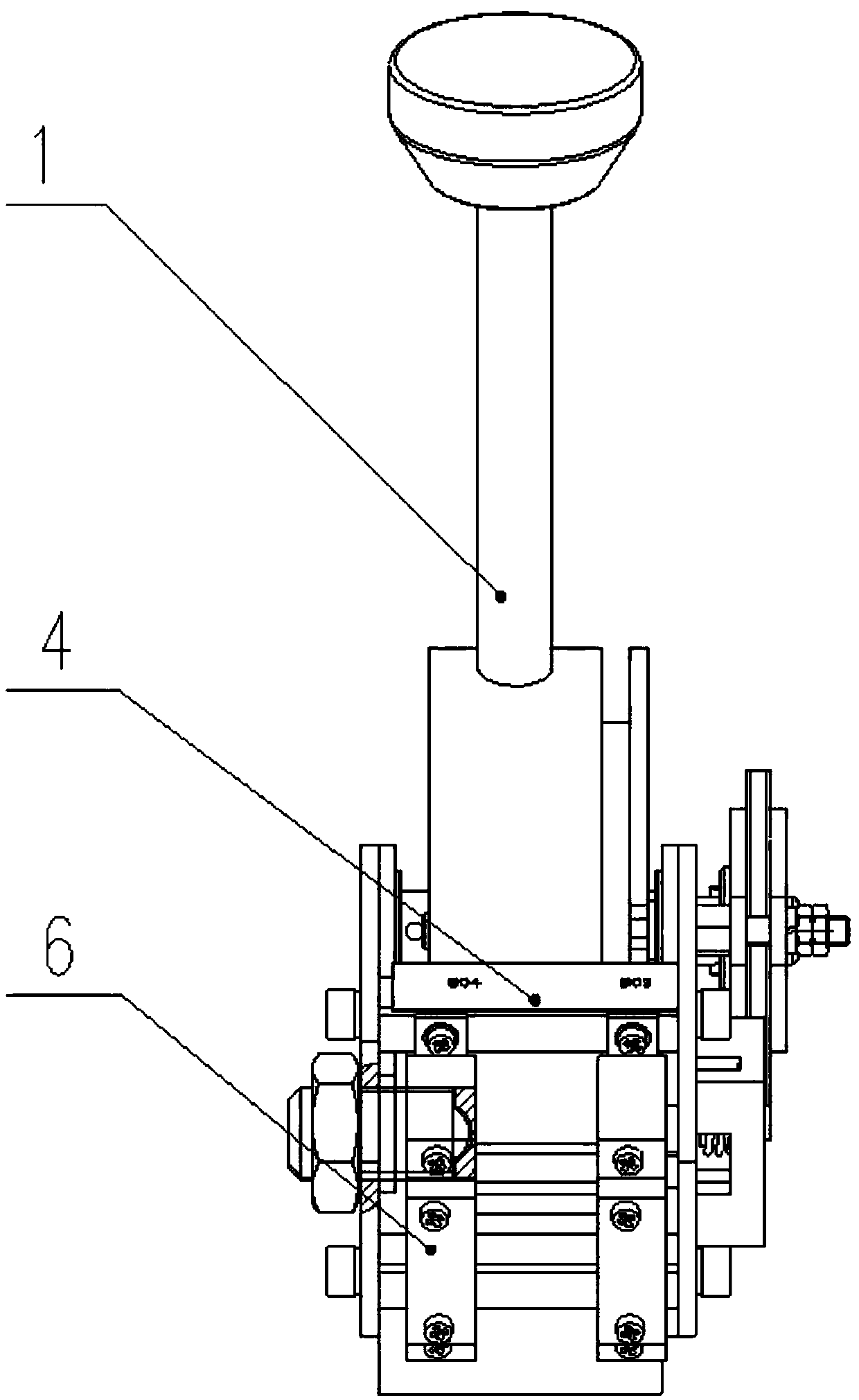
technical field [0001] The invention belongs to the field of locomotive brake systems, in particular to a one-way reset mechanism for a locomotive brake controller and a brake controller. Background technique [0002] Both the "overcharge" position of the large brake unit of the locomotive brake controller and the "relief" position of the small brake unit are equipped with a one-way self-resetting mechanism. From figure 1 and figure 2 It can be seen from the structural diagram of the existing locomotive brake controller that the existing one-way self-resetting mechanism is composed of multiple components such as a reset pull rod 5, a limit post 7, a reset post, a tension spring, and a reset base 10. Its elastic force reset mechanism is installed on the side plate 3 of the frame 4, and other auxiliary components are installed on the rotating parts of the large gate unit or the small gate unit, which is not an integral module structure. [0003] Taking the small gate unit ...

Claims


Application Information

Patent Timeline
IPC IPC(8): B61H13/02B60T7/10
CPCB60T7/10B61H13/02
Inventor 胡楚联林平饶攀王雄波历洋莫文芳
Owner ZHUZHOU ELECTRIC LOCOMOTIVE CO
Learn More