Automatic discharging, moving and swinging device of geological exploration drill pipe

An automatic drainage and geological exploration technology, applied in the direction of drill pipe, drill pipe, drilling equipment, etc., can solve the problems of low installation flexibility, time-consuming and labor-intensive, affecting production and use, and achieve a high degree of automation, increase the selection range, improve The effect of stability

Inactive Publication Date: 2019-03-29
陈小龙
View PDF0 Cites 1 Cited by
  • Summary
  • Abstract
  • Description
  • Claims
  • Application Information

AI Technical Summary

Problems solved by technology

[0003] However, the current discharge and swing equipment has a complex structure, and the vertical steering steps of sending out the drill pipe and the mechanical arm are too cumbersome, and because the drilling position of the drill pipe rack is generally fixed, this requires that the drill pipe on the mechanical arm must be rotated and fixed. The position of the drill pipe rack is matched, the instal

Method used


Image

  • Automatic discharging, moving and swinging device of geological exploration drill pipe
  • Automatic discharging, moving and swinging device of geological exploration drill pipe
  • Automatic discharging, moving and swinging device of geological exploration drill pipe

Examples


Embodiment 1

[0036] The following is a description of Embodiment 1.

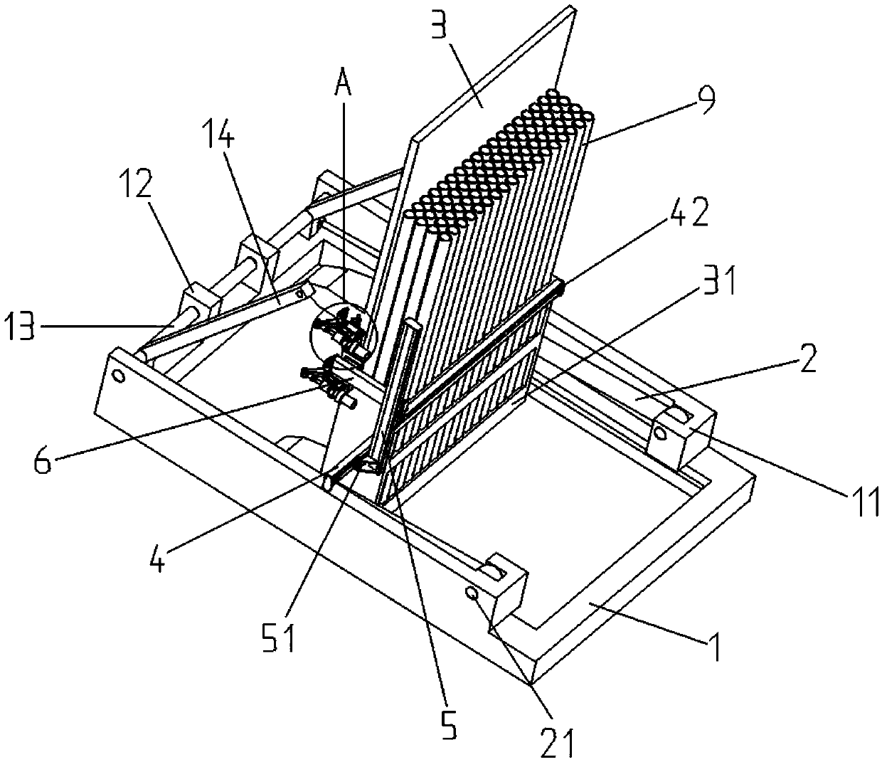
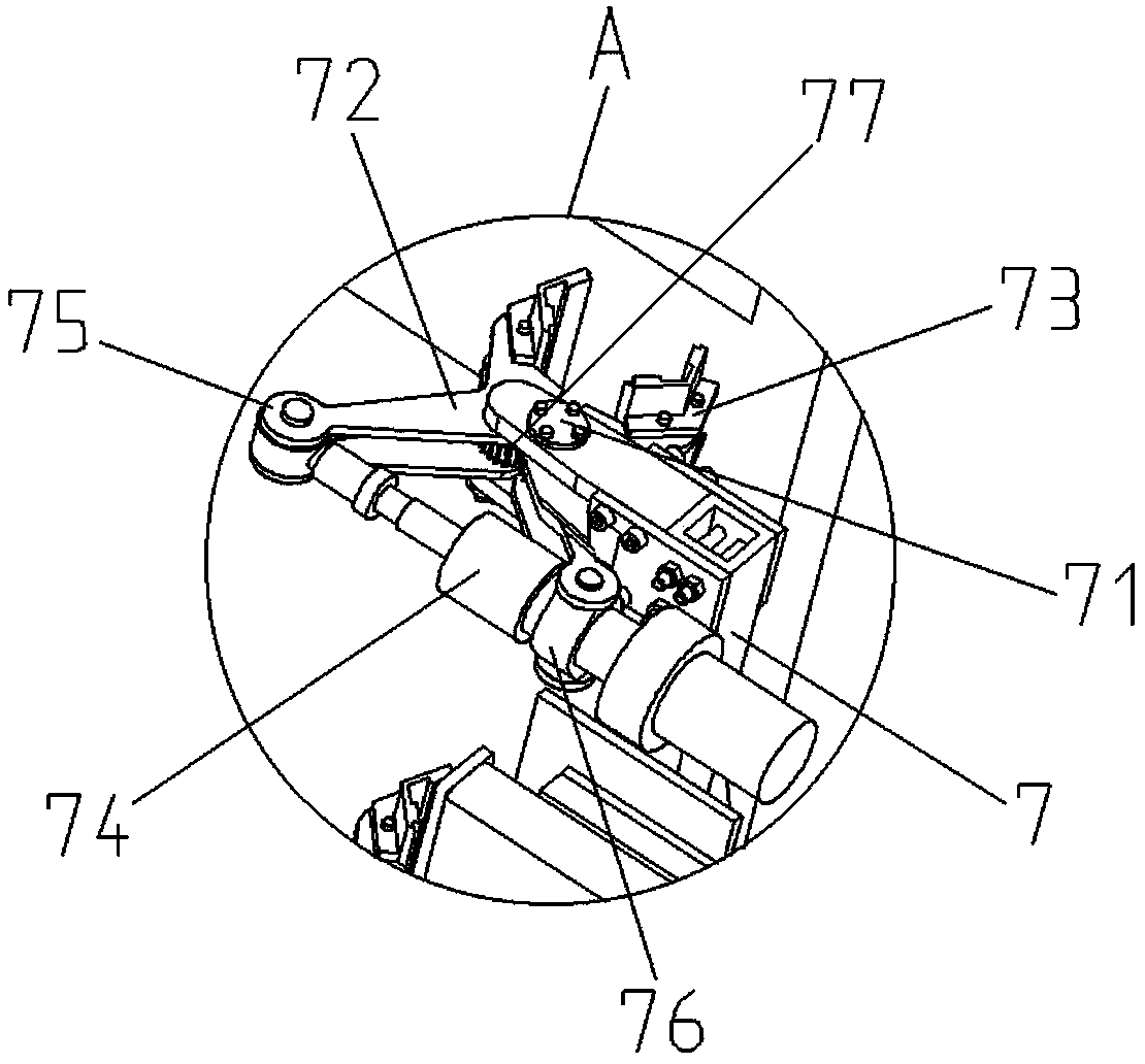
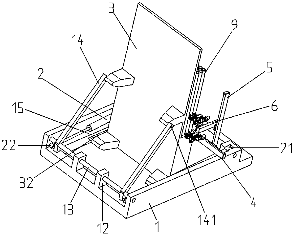
[0037] Such as Figures 1 to 8 As shown, an automatic discharge and swing device for geological exploration drill pipes includes an underframe body 1, a hydraulic cylinder shaft groove 11, an underframe positioning block 12, a support frame shaft 13, a support drive block 131, a vertical support frame 14, Connect the support shaft 141, slide groove 15, vertical drive hydraulic cylinder 2, hydraulic cylinder installation shaft 21, cylinder rod drive shaft 22, drill pipe vertical frame 3, vertical limit frame 31, limit slide rod 32, lateral slide Frame 4, horizontal rotary motor 41, horizontal screw rod 42, vertical sliding frame 5, horizontal slider 51, vertical rotary motor 52, vertical screw rod 53, lateral sliding frame 6, vertical slider 61, lateral rotary motor 62. Lateral screw 63, clamping mounting frame 7, clamping body shaft assembly 71, clamping body power arm 72, clamping claw 73, clamping driving cylinder 74,...

Embodiment 2

[0045] The following is a description of Embodiment 2.

[0046] In embodiment 2, for the same structure as in embodiment 1, the same symbol is given, and the same description is omitted. Embodiment 2 is improved on the basis of embodiment 1. A level sensor module perpendicular to the end face of the drill pipe vertical frame 3 is provided, and the level sensor module is electrically connected to the input end of the single-chip microcomputer control module 8 .

[0047] The benefit of this embodiment is: whether the vertical frame 3 of the drilling rod can be detected in real time by the level sensor module to reach the horizontal state, and sent to the single-chip control module 8 in real time, further controlling the start and stop of the vertically driven hydraulic cylinder 2, greatly The delivery accuracy and practicality of the device are improved.

[0048] When the device is in use, connect the power supply external terminal 92, and the vertical drive hydraulic cylinder ...


PUM


Abstract

The invention discloses an automatic discharging, moving and swinging device of a geological exploration drill pipe, and belongs to the technical field of geological drilling. The device comprises a bottom frame body and a drill pipe vertical frame, one end of the bottom frame body is provided with a vertical driving hydraulic cylinder through a shaft, and the vertical driving hydraulic cylinder is connected with a supporting frame shaft arranged at the other end of the bottom frame body through a shaft; the bottom end of the rear portion of the drill pipe vertical frame is arranged in a sliding groove in the inner side of the bottom frame body through a shaft, and the supporting frame shaft is in shaft connection with the middle of the rear portion of the drill pipe vertical frame; a vertical limiting frame is arranged on the front side of the drill pipe vertical frame, a transverse sliding frame is arranged on the outer side of the vertical limiting frame, and a transverse driving module and a vertical sliding frame are arranged in the transverse sliding frame; a vertical driving module and a lateral sliding frame are arranged in the vertical sliding frame, a lateral driving module and a clamping mounting frame are arranged in the lateral sliding frame, and a clamping jaw is arranged on the clamping mounting frame. The problems that existing drill pipe discharging, moving andswinging equipment is tedious in step and low in flexibility are solved, drill pipes to be conveyed in batches can be vertically erected in advance, the drill pipes are clamped by clamping bodies oneby one, and the overall stability is improved.

Description

technical field [0001] The invention relates to an automatic discharge and swing device for geological exploration drilling rods, which belongs to the technical field of geological drilling. Background technique [0002] With the development and wide application of domestic coal machinery and mining machinery and equipment, drill pipes play an important role in mining work as connecting surface drilling rigs and drilling and grinding equipment at the bottom of drilling wells. In the prior art, the drill pipes generally need to be kept vertically in the drill pipe rack to be used by the drilling rig, which usually includes two steps of discharging and shifting: that is, a batch of horizontally placed drill pipes is first sent out through the discharge equipment. A drill pipe is sent out, and then the drill pipe sent out is turned from horizontal to vertical by a large mechanical arm. [0003] However, the current discharge and swing equipment has a complex structure, and the...

Claims


Application Information

Patent Timeline
IPC IPC(8): E21B19/14
CPCE21B19/14
Inventor 陈小龙李伟青
Owner 陈小龙
Why Eureka
Try Eureka