Vehicle rear independent main deceleration assembly

A main reducer, an independent technology, applied in the direction of differential transmission, gear transmission, belt/chain/gear, etc., can solve the difficulty of adjusting the tooth side clearance, reduce the impact resistance of the differential case, and difficult to control And other issues

Pending Publication Date: 2019-03-29
SAIC-GM-WULING AUTOMOBILE CO LTD
View PDF0 Cites 1 Cited by
  • Summary
  • Abstract
  • Description
  • Claims
  • Application Information

AI Technical Summary

Problems solved by technology

[0002] The existing independent main reducer assembly is connected with two planetary gears respectively in the differential housing inside the differential housing in the differential assembly in the driving device, so that each Each planetary gear bears a relatively large force, and the main tooth converts the rapid rotation into the slow rotation of the differential half shaft, reducing the rotation speed. During this process, the torque increases and the direction of the torque is changed. The planetary gear changes the torque in the process The torque transmission is not stable, which makes the two differential half shafts connected to it vibrate and vibrate, resulting in howling and resonance, which reduces the NVH performance and ride comfort of the vehicle
Moreover, the size of the assembly process hole opened on the

Method used


Image

  • Vehicle rear independent main deceleration assembly
  • Vehicle rear independent main deceleration assembly
  • Vehicle rear independent main deceleration assembly

Examples


Embodiment Construction

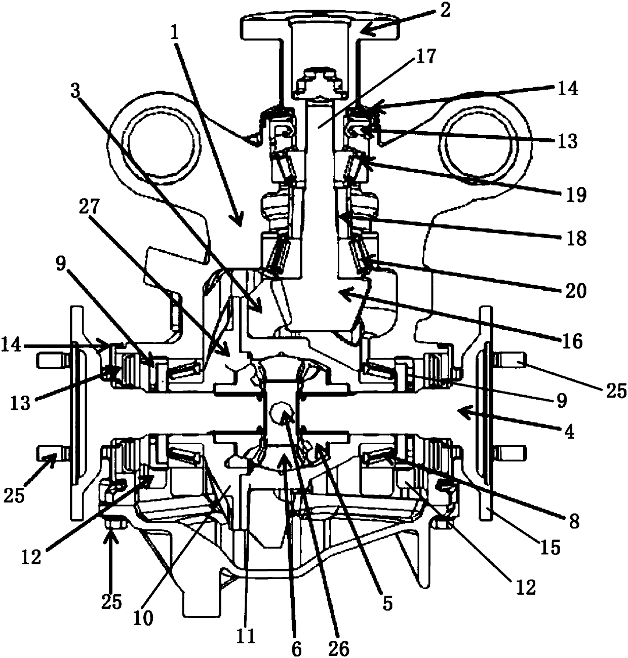
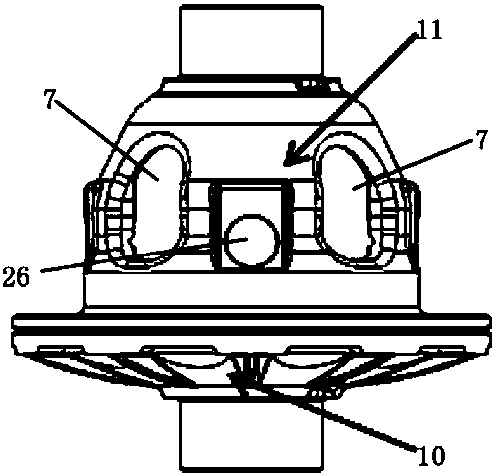
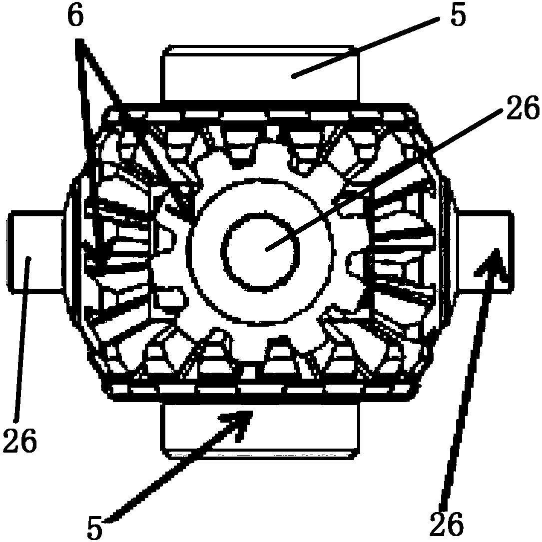
[0031] The following with attached Figure 1 to Figure 6 An automobile rear independent final reducer assembly of the present invention is further described in detail.

[0032] An automobile rear independent main reducer assembly of the present invention, please refer to Figure 1 to Figure 6The relevant figures in the figure include the connecting flange 2, the final reducer housing 1, the main gear set in the final reducer housing 1, the secondary gear 3, the differential assembly and the The differential half shaft 4 on the left and right sides of the differential assembly, the connecting flange 2 is fixed to the main tooth, the main tooth is a bevel gear, and the passive tooth 3 is fixed to the main tooth , the central axes of the main teeth and the passive teeth 3 are perpendicular to each other, and the differential assembly includes a differential case, side gears 5 located at the left and right ends of the differential case, and Four planetary gears 6 between the two...


PUM


Abstract

The invention discloses a vehicle rear independent main deceleration assembly. The vehicle rear independent main deceleration assembly comprises a connecting flange, a main decelerator shell, a driving tooth, a driven tooth, a differential machine assembly, and differential semi-shafts. The connecting flange is fixed to the driving tooth. The driven tooth is engaged with and fixed to the driving tooth. The differential machine assembly comprises a differential machine shell, two semi-shaft gears, and four planetary gears. The planetary gears are perpendicular to the two semi-shaft gears. Eachplanetary gear is engaged with and connected to one lateral faces of the two semi-shaft gears separately. The planetary gears are rotatably arranged in the differential machine shell. The other lateral ends of the semi-shaft gears are separately fixedly connected with the corresponding differential semi-shafts in a detachable mode. The differential semi-shafts are separately detachably fixed to corresponding tires. The driven tooth is detachably fixed to the outer edge of the differential machine shell. According to the vehicle rear independent main deceleration assembly, the structure is simple, noise during vehicle driving can be effectively reduced, the service life of the planetary gears can be effectively prolonged, torque transmission is stable, resonance is avoided, and NVH performance and riding comfort of the whole vehicle are effectively improved.

Description

technical field [0001] The invention relates to a main speed reducer, in particular to an automobile rear independent main speed reducer assembly. Background technique [0002] The existing independent main reducer assembly is connected with two planetary gears respectively in the differential housing inside the differential housing in the differential assembly in the driving device, so that each Each planetary gear bears a relatively large force, and the main tooth converts the rapid rotation into the slow rotation of the differential half shaft, reducing the rotation speed. During this process, the torque increases and the direction of the torque is changed. The planetary gear changes the torque in the process The torque transmission is not stable, causing the two differential axle shafts connected to it to vibrate and vibrate, resulting in howling and resonance, which reduces the NVH performance and ride comfort of the vehicle. Moreover, the size of the assembly process ...

Claims


Application Information

Patent Timeline
IPC IPC(8): F16H3/44F16H48/08F16H48/36F16H48/40F16H57/023F16H57/028
CPCF16H3/44F16H48/08F16H48/36F16H48/40F16H57/023F16H57/028F16H2048/368
Inventor 韦进光任良顺王申
Owner SAIC-GM-WULING AUTOMOBILE CO LTD
Why Eureka
Try Eureka