Public building kitchen oil smoke exhausting pipeline system

A pipeline system and public building technology, which is applied in the field of public building kitchen oil fume exhaust pipeline system, can solve the problems of negative impact on the city image, difficult to clean, ugly appearance, etc., and achieve the effect of improving the city image, reducing pollution, and simplifying the installation steps

Inactive Publication Date: 2019-03-29
江苏华源建筑设计研究院股份有限公司
View PDF5 Cites 0 Cited by
  • Summary
  • Abstract
  • Description
  • Claims
  • Application Information

AI Technical Summary

Problems solved by technology

[0003] Although the use of the oil fume exhaust system can reduce indoor wall pollution, when the exhausted oil fume comes into contact with other buildings, it will condense on the surface of these buildings
Especially in some large canteens of public buildings, the daily amount of soot is very large. In our daily life, we can often see the outer walls of these public building canteens and the outer walls of surrounding buildings. oil stains, and these oil stains are very viscous, and at the same time they are located in a high position of the building, so they are very difficult to clean
These stains give people a very ugly impression. International friends will leave a messy impression when they arrive, which will have a negative impact on the image of the city.

Method used


Image

  • Public building kitchen oil smoke exhausting pipeline system
  • Public building kitchen oil smoke exhausting pipeline system
  • Public building kitchen oil smoke exhausting pipeline system

Examples


Embodiment Construction

[0034] The present invention will be described in further detail below in conjunction with the accompanying drawings.

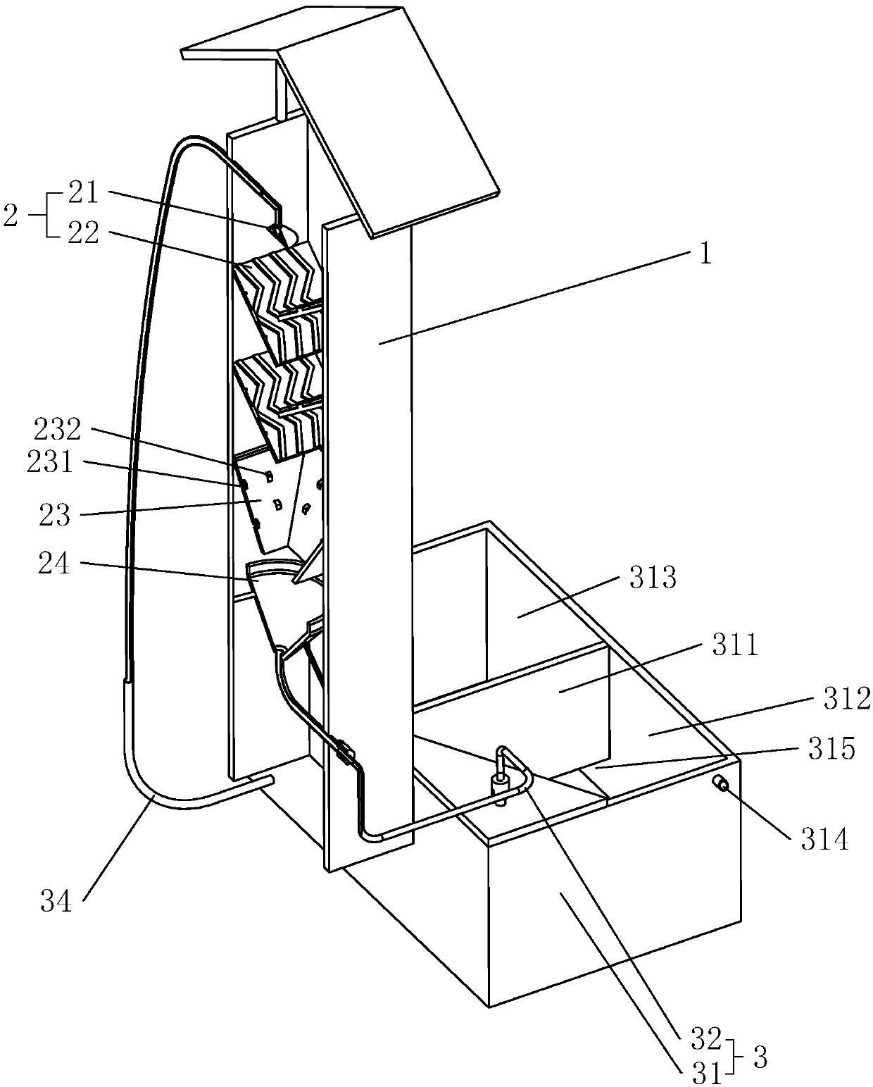
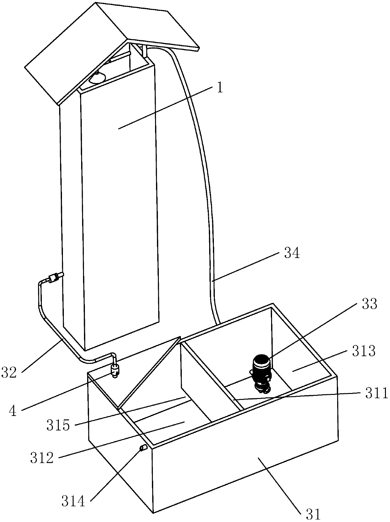
[0035] Such as figure 1 As shown, a cooking fume exhaust pipeline system in a public building includes a pipeline main body 1 and a fume filter device 2. The pipeline main body 1 is used to be installed on the outer wall of the building, and is mainly connected with the kitchen range hood pipeline, and guides The fume from the range hood is discharged into the upper atmosphere.

[0036] Oil fume filter device 2 spray head 21, liquefaction plate 22, water diversion bucket 23, and dirt bucket 24, the spray head 21 is fixed in the pipeline main body 1, and is close to the gas outlet of the pipeline main body 1; the liquefaction plate 22 is provided with at least two sets , the number of each group is more than two, the liquefaction plate 22 is fixed on the inner wall of the pipeline main body 1, and is located under the sprinkler head 21; two groups of liquefac...


PUM


Abstract

The invention discloses a public building kitchen oil smoke exhausting pipeline system and relates to the smoke processing technology. The public building kitchen oil smoke exhausting pipeline systemis used for solving the problem that oil smoke discharged by a large-scale canteen can pollute the surrounding building. The public building kitchen oil smoke exhausting pipeline system comprises a pipeline main body and an oil smoke filtering device, wherein the oil smoke filtering device is arranged in the pipeline main body; the oil smoke filtering device comprises a spraying head, liquefied plates and a dirt receiving bucket, the spraying head is arranged in the pipeline main body and is close to the air outlet of the pipeline main body, the liquefied plates are fixed in the pipeline mainbody and are arranged at intervals, the dirt receiving bucket is arranged in the pipeline main body and is used for receiving condensed water sprayed out by the spraying head, the number of the liquefied plates is at least two groups, the two groups of the liquefied plates are distributed in a staggered mode, and the ends, close to each other, of the two groups of liquefied plates are obliquely arranged downwards. The public building kitchen oil smoke exhausting pipeline system has the following advantages and effects that the oil smoke filtering device can clean flue gas, grease which wraps the flue gas is removed, the grease does not easily float out of the pipeline body and is liquefied on the outer wall surface of the surrounding buildings, pollution to the building caused by oil stains is reduced, and therefore the purpose of improving a city image is achieved.

Description

technical field [0001] The invention relates to smoke treatment technology, in particular to a cooking fume exhaust pipe system for public buildings. Background technique [0002] During the use of the kitchen, cooking oil is easy to volatilize when heated. The oily fume will be liquefied by cooling and condensed on the surface of these objects after encountering objects with low temperature such as walls. Therefore, under normal circumstances, the kitchen will install a smoke exhaust system. The oily fumes are extracted and discharged outdoors. [0003] Although the use of the oil fume exhaust system can reduce indoor wall pollution, when the exhausted oil fume comes into contact with other buildings, it will condense on the surfaces of these buildings. Especially in some large canteens of public buildings, the daily amount of soot is very large. In our daily life, we can often see the outer walls of these public building canteens and the outer walls of surrounding buildin...

Claims


Application Information

Patent Timeline
IPC IPC(8): F24C15/20
Inventor 梁震
Owner 江苏华源建筑设计研究院股份有限公司
Why Eureka
Try Eureka